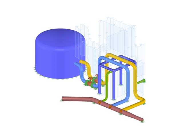
- Graphical input of piping systems and piping components
- Illustrative visualization of piping systems and piping components in RFEM graphic window
- Comprehensive libraries for piping cross‑sections and materials
- Comprehensive libraries for flanges, reducers, tees, and expansion joints
- Consideration of piping structure (insulation, lining, tin‑plate)
- Automatic calculation of stress intensification factors and flexibility factors
- Specific piping action categories for load cases
- Optional automatic combinatorics of load cases
- Consideration of material properties (modulus of elasticity, coefficient of thermal expansion) either during operating temperature (default setting) or during reference (assembly) temperature of material
- Consideration of strain and uplift due to pressure (Bourdon effect)
- Interaction between the supporting structure and the piping system
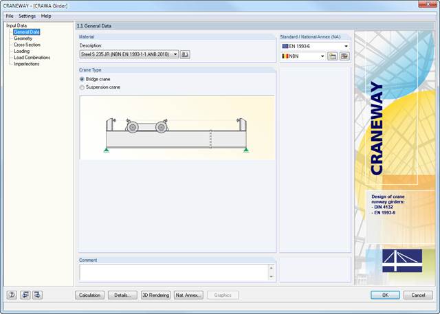
Geometry, material, cross-section, action, and imperfection data are entered in clearly arranged input windows:
Geometry
- Quick and convenient data input
- Definition of support conditions based on various support types (hinged, hinged movable, rigid, and user-defined, as well as lateral on upper or bottom flange)
- Optional specification of warping restraint
- Variable arrangement of rigid and deformable support stiffeners
- Possibility to insert hinges
CRANEWAY Cross-Sections
- I-shaped rolled cross-sections (I, IPE, IPEa, IPEo, IPEv, HE-B, HE-A, HE-AA, HL, HE-M, HE, HD, HP, IPB-S, IPB-SB, W, UB, UC, and other cross-sections according to AISC, ARBED, British Steel, Gost, TU, JIS, YB, GB, and others) combinable with section stiffener on the upper flange (angles or channels) as well as rail (SA, SF) or splice with user-defined dimensions
- Unsymmetrical I-sections (type IU) also combinable with stiffeners on the upper flange as well as with rail or splice
Actions
It is possible to consider the actions of up to three simultaneously operated cranes. You can simply select a standard crane from the library. You can also enter data manually:
- Number of cranes and crane axles (maximum of 20 axles per crane), center distances, position of crane buffers
- Classification in damage classes with editable dynamic factors according to EN 1993-6, and in lifting classes and exposure categories according to DIN 4132
- Vertical and horizontal wheel loads from self-weight, hoist load, mass forces from drive, as well as loads from skewing
- Axial loading in driving direction as well as buffer forces with user-defined eccentricities
- Permanent and variable secondary loads with user-defined eccentricities
Imperfections
- The imperfection load applies in compliance with the first natural vibration mode - either identically for all load combinations to be designed, or individually for each load combination, as mode shapes may vary depending on the load.
- Convenient tools available for scaling the mode shapes (rise determination of inclination and precamber).
Foundations are assigned graphically by selecting supports using the [Select] function in the graphical user interface of RFEM/RSTAB and by specifying the load cases to be designed. You can define all other foundation details quickly and easily in clearly arranged input windows.
In addition to all support forces from RFEM/RSTAB, you can specify further loads to be considered when dimensioning the foundations. The following additional loadings are available:
- Pemanent surface load due to earth covering
- Negative surface load; for example, due to traffic
- Ground water level for uplift consideration
- Concentrated loads in any position on the foundation plate
- Line loads with any distribution over the foundation plate
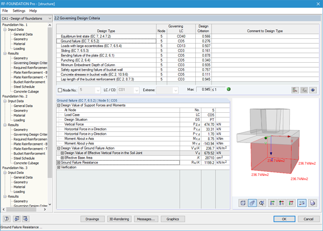
It is possible to perform the following designs:
- Equilibrium limit state design
- Uplift limit state design
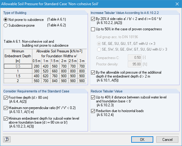
- Ground failure (soil contact pressure) design
- Strong eccentric loads design
- Design of foundation torsion and limitation of gaping joint
- Sliding design
- Settlement calculation
- Bending failure design of the plate and bucket
- Punching shear design
Foundation and bucket dimensions can be user-defined or determined by the module. You can edit the determined reinforcement manually. In this case, the designs are updated automatically.