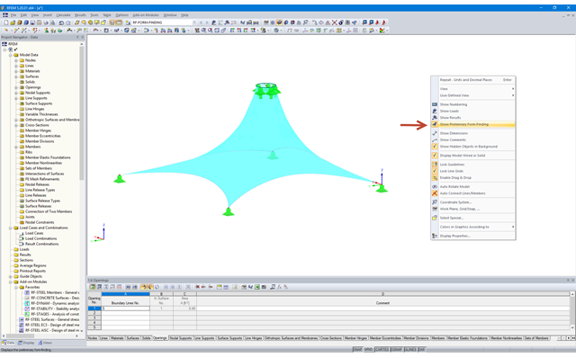
Activating 'Show Form-Finding' in the shortcut menu leads to an automatic preliminary form-finding according to the saved form-finding properties when you change the structure of membrane surfaces. This interactive graphics mode is based on the force density method.
More Information FAQ.png?mw=640&hash=688fdfc8af4828c08e9851cddb103a1e86cb899a)
- Form-finding of:
- tension-loaded membrane and cable structures
- compression-loaded shell and beam structures
- mixed tension- and compression-loaded structures
- Consideration of gas chambers between surfaces
- Interaction with supporting structure (substructure design according to various standards)
- Surfaces as a 2D and members as a 1D element
- Definition of different prestress conditions for surfaces (membranes and shells)
- Definition of forces or geometrical requirements for members (cables and beams)
- Consideration of individual loads (self‑weight, inner pressure, and so on) in the form‑finding process
- Temporary support definitions for the form-finding process
- Automatic preliminary form-finding of membrane surfaces (more information...)
- Definition of isotropic or orthotropic material for structural analysis
- Optional definition of free polygon loads
- Transformation of form‑found shape elements into NURBS surface elements
- Possibility of combined form-finding by integration of preliminary form-finding
- Graphical evaluation of the new form using colored coordinates and inclination plots
- Complete documentation of the calculation including user-defined adaptive evaluation figures
- Optional export of the FE mesh as a DXF or Excel file
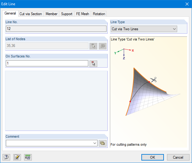
RF-CUTTING-PATTERN is activated by selecting the respective option in the Options tab in General Data of any RFEM model. After activating the add‑on module, a new object, "Cutting Patterns", is displayed under Model Data. If the membrane surface distribution for cutting in the basic position is too large, you can divide the surface by cutting lines (line types "Cut via Two Lines" or "Cut via Section") in the corresponding partial strips.
Then you can define the individual entries for each cutting pattern using the "Cutting Pattern" object. Here you can set boundary lines, compensations, and allowances.
Steps of the working sequence:
- Creation of cutting lines
- Creation of the pattern by selecting its boundary lines or using a semi‑automatic generator
- Free selection of warp and weft orientation by entering an angle
- Application of compensation values
- Optional definition of different compensations for boundary lines
- Different allowances (welding, boundary line)
- Preliminary representation of the cutting pattern in the graphic window at the side without starting the main nonlinear calculation
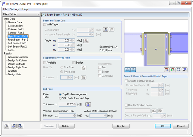
The RF-/FRAME-JOINT Pro add-on module designs connections of structures calculated in RFEM/RSTAB. If there is no RFEM/RSTAB structure available, you can define the geometry and loading manually; for example, when checking external calculations, for example.
Designed nodes are usually imported from RFEM/RSTAB. The module recognizes all connected members automatically and assigns a connection type to them. Depending on the connection type, you can define further details of ribs, backing plates, web plates, bolts, welds, and hole spacing. As loads, you can select any load case, load combination or result combination in RFEM/RSTAB.
In the case of the "preliminary design" calculation mode, RF-/FRAME-JOINT Pro performs the first calculation step to suggest applicable layouts. After you select the relevant layout, the module displays all designs in detailed result tables and various graphics.

- Design of knee joints, T-joints, cross joints, and continuous column connections with I-shaped sections
- Import of geometry and load data from RFEM/RSTAB or manual specification of the connection (for example, for recalculation without an existing RFEM/RSTAB model)
- Flush top connections or connections with bolt row in extension
- Design of positive and negative frame joint moments
- Various inclinations of right and left horizontal beams as well as application to frames of duopitch and monopitch roofs
- Consideration of additional flanges in a horizontal beam, for example for tapered sections
- Symmetrical and asymmetrical T-joints or cross joints
- Two-sided connection with different cross-section depth on the right and left
- Automatic preliminary design of bolt layout and required stiffening
- Optional design mode with possibility to specify all bolt spacing, welds, and sheet thicknesses
- Screwability check with adjustable dimensions of used wrenches
- Connection classification by stiffness and calculation of the spring stiffness of connections considered in the internal forces determination
- Check up to 45 individual designs (components) of the connection
- Automatic determination of governing internal forces for each individual design
- Controllable connection graphics in rendering mode with specifications of material, sheet thickness, welds, bolt spacing, and all dimensions for construction
- Integrated and flexibly extensible settings of National Annexes according to EN 1993-1-8 standard
- Automatic conversion of internal forces from structural analysis into respective sections, also for eccentric member connections
- Automatic determination of initial stiffness Sj,ini of the connection
- Detailed plausibility check of all dimensions, including specifications of input limits (for example, for edge distances and hole spacing)
- Optional application of compression forces to a column through contact
- Possibility to update the cross-section depth of horizontal beams in case of tapered connections after connection geometry optimization in RF-/FRAME-JOINT Pro