
- Design of five types of seismic force-resisting systems (SFRS) includes Special Moment Frame (SMF), Intermediate Moment Frame (IMF), Ordinary Moment Frame (OMF), Ordinary Concentrically Braced Frame (OCBF), and Special Concentrically Braced Frame (SCBF)
- Ductility check of the width-to thickness ratios for webs and flanges
- Calculation of the required strength and stiffness for stability bracing of beams
- Calculation of the maximum spacing for stability bracing of beams
- Calculation of the required strength at hinge locations for stability bracing of beams
- Calculation of the column required strength with the option to neglect all bending moments, shear, and torsion for overstrength limit state
- Design check of column and brace slenderness ratios

It is necessary to enter the required force-time diagrams. They can be combined in load cases or load combinations of the type Time History Analysis | Time Diagrams with the loading in order to define where and in which direction the force-time diagrams act.
The second option is to enter acceleration-time diagrams, which can be used in the load cases of the Time History Analysis | Accelerogram type.
All calculation parameters are specified in the time history analysis settings. These include, for example, the type of analysis method and the maximum calculation time.

With the Concrete Design add-on, you can perform the fatigue design of members and surfaces according to EN 1992‑1‑1, Chapter 6.8.
For the fatigue design, you can optionally select two methods or design levels in the design configurations:
- Design Level 1: Simplified design according to 6.8.6 and 6.8.7(2): The simplified design is performed for frequent action combinations according to EN 1992‑1‑1, Chapter 6.8.6 (2), and EN 1990, Eq. (6.15b) with the traffic loads relevant in the serviceability state. A maximum stress range according to 6.8.6 is designed for the reinforcing steel. The concrete compressive stress is determined by means of the upper and lower allowable stress according to 6.8.7(2).
- Design Level 2: Design of damage equivalent stress acc. to 6.8.5 and 6.8.7(1) (simplified fatigue design): The design using damage equivalent stress ranges is performed for the fatigue combination according to EN 1992‑1‑1, Chapter 6.8.3, Eq. (6.69) with the specifically defined cyclic action Qfat.

Would you like to create a cross-section from the import of a DXF file? It's very easy. You have the following options:
- Create elements automatically
- Use DXF template lines as centerlines of elements with a defined thickness
Do you select the option to create the elements automatically? In that case, the program creates the elements and the associated parts for you from the contour of the outline. It only creates the elements not exceeding a definable maximum thickness.
Your cross-section geometry is available as a centroidal axis model? Then use DXF template lines as centerlines of elements with a defined thickness. Defining a thickness that is assigned equally to all elements.
Do you miss the "Create elements automatically" and "Create elements on lines" functions? Don't worry, both are also available in the "Edit" menu under "Manipulation".

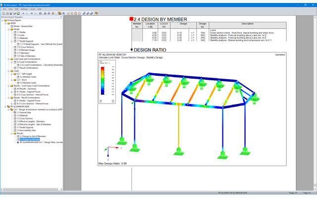
The program does a lot of work for you. For example, the load or result combinations required for the serviceability limit state are generated and calculated in RFEM/RSTAB. You can select these design situations for the deflection analysis in the Aluminum Design add-on. Depending on the specified precamber and reference system, the program determines the deformation values at each location of a member. They are then compared to the limit values.
You can specify the deformation limit value individually for each structural component in Serviceability Configuration. In this case, you define the maximum deformation depending on the reference length as the allowable limit value. By defining design supports, you can segment the components. In this way, you can determine the corresponding reference length automatically for each design direction.
And that's not all. Based on the position of the assigned design supports, the program allows you to automatically determine the distinction between beams and cantilevers. The limit value is thus determined accordingly.

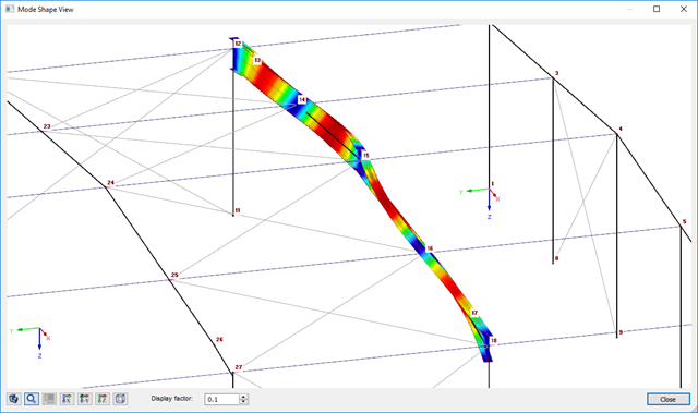
As you've already learned, the results of a Modal Analysis load case are displayed in the program after a successful calculation. You can thus immediately see the first mode shape graphically or as an animation. You can also easily adjust the representation of the mode shape standardization. Do that directly in the Results navigator, where you have one of four options for the visualization of the mode shapes available for the selection:
- Scaling the value of the mode shape vector uj to 1 (considers the translation components only)
- Selecting the maximum translational component of the eigenvector and setting it to 1
- Considering the entire eigenvector (including the rotation components), selecting the maximum, and setting it to 1
- Setting the modal mass mi for each mode shape to 1 kg
You can find a detailed explanation of the mode shape standardization in the OnlineManual here.

Is your goal to determine the number of mode shapes? The program offers you two methods for this. On the one hand, you can manually define the number of the smallest mode shapes to be calculated. In this case, the number of available mode shapes depends on the degrees of freedom (that is, the number of free mass points multiplied by the number of directions in which the masses act). However, it is limited to 9999. On the other hand, you can set the maximum natural frequency the way that the program determined the mode shapes automatically until reaching the natural frequency set.

Your RFEM/RSTAB program is responsible for generating and calculating the load and result combinations required for the serviceability limit state. Select the design situations for the deflection analysis in the Timber Design add-on. The calculated deformation values are then determined at each location of a member, depending on the specified precamber and the reference system, and then compared to the limit values.
You can specify the deformation limit value individually for each structural component in Serviceability Configuration. In this case, the maximum deformation should not exceed the permissible limit value, depending on the reference length. When defining design supports, you can segment the components. This allows you to determine the corresponding reference length automatically for each design direction.
Based on the position of the assigned design supports, the program automatically determines the difference between beams and cantilevers. Thus, you can be sure that the limit value is determined accordingly.

In RFEM/RSTAB, you have the option to generate and then calculate the load or result combinations required for the serviceability limit state. You can select these design situations for the deflection analysis in the Steel Design add-on. The calculated deformation values are determined accordingly at each location of a member, depending on the specified precamber and reference system. Finaly, you can compare these deformation values with the limit values.
Did you know? You can specify the deformation limit value individually for each structural component in Serviceability Configuration. Define the maximum deformation depending on the reference length as the allowable limit value. By defining design supports, you can segment the components in order to determine the corresponding reference length automatically for each design direction.
Based on the position of the assigned design supports, the distinction between beams and cantilevers is made automatically so the limit value can be determined accordingly.

Compared to the RF-FORM-FINDING add-on module (RFEM 5), the following new features have been added to the Form-Finding add-on for RFEM 6:
- Specification of all form-finding load boundary conditions in one load case
- Storage of form-finding results as initial state for further model analysis
- Automatic assignment of the form-finding initial state via combination wizards to all load situations of a design situation
- Additional form-finding geometry boundary conditions for members (unstressed length, maximum vertical sag, low-point vertical sag)
- Additional form-finding load boundary conditions for members (maximum force in member, minimum force in member, horizontal tension component, tension at i-end, tension at j-end, minimum tension at i-end, minimum tension at j-end)
- Material types "Fabric" and "Foil" in material library
- Parallel form-findings in one model
- Simulation of sequentially building form-finding states in connection with the Construction Stages Analysis (CSA) add-on

Compared to the RF‑/DYNAM Pro - Natural Vibrations add-on module (RFEM 5 / RSTAB 8), the following new features have been added to the Modal Analysis add-on for RFEM 6 / RSTAB 9:
- Preset combination coefficients for various standards (EC 8, ASCE, and so on)
- Optional neglect of masses (for example, mass of foundations)
- Methods for determining the number of mode shapes (user-defined, automatic - to reach effective modal mass factors, automatic - to reach the maximum natural frequency)
- Output of modal masses, effective modal masses, modal mass factors, and participation factors
- Masses in mesh points displayed in tables and graphics
- Various scaling options for mode shapes in the Result navigator

Was your design successful? Then just sit back and relax. You benefit from the numerous functions in RFEM also here. The program gives you the maximum stresses of the masonry surfaces, whereby you can display the results in detail at each FE mesh point.
Moreover, you can insert sections in order to carry out a detailed evaluation of the individual areas. Use the display of the yield areas to estimate the cracks in the masonry.

- Automatic consideration of masses from self-weight
- Direct import of masses from load cases or load combinations
- Optional definition of additional masses (nodal, linear, or surface masses, as well as inertia masses) directly in the load cases
- Optional neglect of masses (for example, mass of foundations)
- Combination of masses in different load cases and load combinations
- Preset combination coefficients for various standards (EC 8, SIA 261, ASCE 7,...)
- Optional import of initial states (for example, to consider prestress and imperfection)
- Structure Modification
- Consideration of failed supports or members/surfaces/solids
- Definition of several modal analyses (for example, to analyze different masses or stiffness modifications)
- Selection of mass matrix type (diagonal matrix, consistent matrix, unit matrix), including user-defined specification of translational and rotational degrees of freedom
- Methods for determining the number of mode shapes (user-defined, automatic - to reach effective modal mass factors, automatic - to reach the maximum natural frequency - only available in RSTAB)
- Determination of mode shapes and masses in nodes or FE mesh points
- Results of eigenvalue, angular frequency, natural frequency, and period
- Output of modal masses, effective modal masses, modal mass factors, and participation factors
- Masses in mesh points displayed in tables and graphics
- Visualization and animation of mode shapes
- Various scaling options for mode shapes
- Documentation of numerical and graphical results in printout report

In the modal analysis settings, you have to enter all data that are necessary for the determination of the natural frequencies. These are, for example, mass shapes and eigenvalue solvers.
The Modal Analysis add-on determines the lowest eigenvalues of the structure. Either you adjust the number of eigenvalues or let them determined automatically. Thus, you should reach either effective modal mass factors or maximum natural frequencies. Masses are imported directly from load cases and load combinations. In this case, you have the option to consider the total mass, load components in the global Z-direction, or only the load component in the direction of gravity.
You can manually define additional masses at nodes, lines, members, or surfaces. Furthermore, you can influence the stiffness matrix by importing axial forces or stiffness modifications of a load case or load combination.

Have you created the entire structure in RFEM? Very well, now you can assign the individual structural components and load cases to the corresponding construction stages. In each construction stage, you can modify release definitions of members and supports, for example.
You can thus model structural modifications, such as those that occur when bridge girders are successively grouted or when columns are settled. Then, assign the load cases created in RFEM to the construction stages as permanent or non-permanent loads.
Did you know that The combinatorics allows you to superimpose the permanent and non-permanent loads in load combinations. In this way, it is possible for you to determine the maximum internal forces of different crane positions or to consider temporary mounting loads available in one construction stage only.

After you have completed the design, the program takes care of clearly arranged results. Thus, the program shows you the resulting maximum stresses and stress ratios sorted by section, member/surface, solid, member set, x-location, and so on. In addition to the tabular result values, the add-on shows you the corresponding cross-section graphic with stress points, stress diagram, and values as well. You can relate the design ratio to any kind of stress type. The current location is highlighted in the RFEM/RSTAB model.
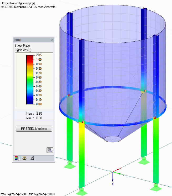
In addition to the tabular evaluation, the program offers you even more. You can also graphically check the stresses and design ratios on the RFEM/RSTAB model. It is possible for you to adjust the colors and values individually.
The display of result diagrams of a member or set of members enables you a targeted evaluation. For each design location, you can open the respective dialog box to check the design-relevant section properties and stress components of any stress point. Finally, you have the option of printing the corresponding graphic, including all design details.
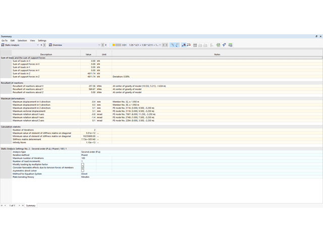
With clearly arranged tables, you can always keep an eye on your results. The first result table displays a summarized overview providing the equilibrium of forces in the structural system and the maximum deformations. Moreover, you also get the information about the calculation process. You can filter the result tables by specific criteria, such as extreme values or design locations, in order to obtain a better overview.
- Footfall Analysis links with RFEM, using the model geometry from there, thus the user is not required to create a second model specifically for footfall analysis
- Allows the user to analyze any type of structure for footfall analysis, irrespective of the shape, material, or use
- Quick and accurate predictions of resonant and impulsive (transient) responses
- Cumulative measurement of vibration levels – VDV analysis
- Intuitive output enabling the engineer to advise improvements of critical areas in a cost-effective way
- Pass/fail limit check in accordance with BS 6472 and ISO 10137
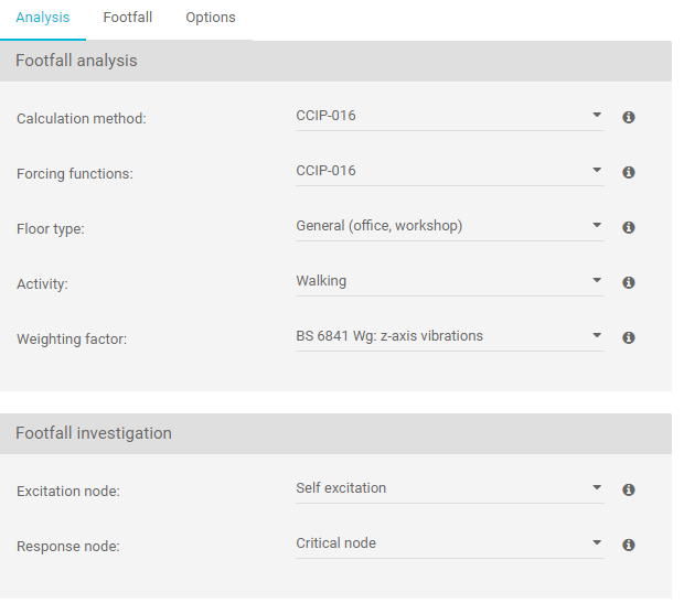
- Selection of excitation forces: CCIP-016, SCI P354, AISC DG11 for floors and stairs
- Frequency weighting curves (BS 6841)
- Quick investigation for full model or specific areas
- Vibration Dose Analysis (VDV)
- Adjusting the minimum and maximum walking frequencies as well as the walker’s weight
- User input damping values
- Varying the number of footfalls for resonant response, user input or software calculated
- Environmental response limit based on BS 6472 and ISO 10137
- Overall maximum response factors and critical nodes
- Resonant analysis (maximum response factor, RMS acceleration, critical node, critical frequency)
- Impulsive (transient) analysis (maximum response factor, peak acceleration/velocity, RMS acceleration/velocity, critical node, critical frequency)
- Vibration dose values for both resonant and impulsive analyses
Charts
- Response factor vs walking frequency
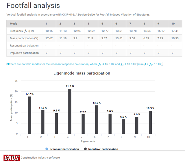
- Mass participation vs eigenmodes
- Velocity time history
After the calculation, the maximum stresses and stress ratios are displayed sorted by sections, members/surfaces, member sets, or x-locations. In addition to the tabular result values, the corresponding cross-section graphic with stress points, stress diagram, and values is displayed as well. The design ratio can be related to any kind of stress type. The current location is highlighted in the RFEM/RSTAB model.
In addition to the result evaluation in the module, it is possible to represent the stresses and stress ratios graphically in the RFEM/RSTAB work window. It is possible to individually adjust the colors and values.
Result diagrams of a member or set of members facilitate targeted evaluation. Furthermore, you can open the respective dialog box of each design location to check the design-relevant section properties and stress components of any stress point. It is possible to print the corresponding graphic, including all design details.
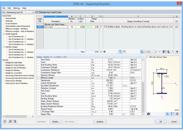
When performing the design of tension, compression, bending, and shear loading, the module compares the design values of the maximum load capacity to the design values of the actions.
If the components are subjected to both bending and compression, the program performs an interaction. In RF-/STEEL EC3, you can determine the factors according to Method 1 (Annex A) or Method 2 (Annex B).
The flexural buckling design requires neither the slenderness nor the elastic critical buckling load of the governing buckling case. The module automatically calculates all required factors for the bending stress design value. RF-/STEEL EC3 determines the elastic critical moment for lateral-torsional buckling for each member on every x-location of the cross-section. If required, you only need to specify lateral intermediate supports of the individual members/sets of members, definable in one of the input windows.
If members are selected for the fire resistance design in RF-/STEEL EC3, there is another input window available where you can enter additional parameters, such as: a coating or cladding type. Global settings cover the required time of fire resistance, temperature curve, and other coefficients. The printout report lists all intermediate results and the final result of the fire resistance design. Furthermore, it is possible to print the temperature curve in the report.
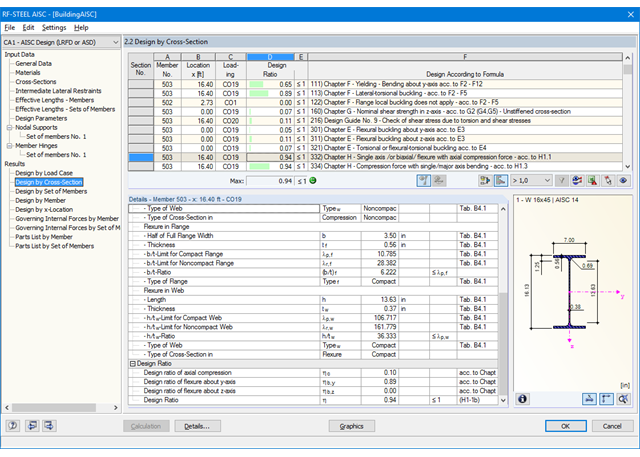
The first result window shows the maximum design ratios with the corresponding design of each designed load case, load combination, or result combination.
The other result windows list all detailed results sorted by specific subject in extendable tree menus. All intermediate results along the members can be displayed at any location. In this way, you can easily retrace how the module has performed the individual designs.
The complete module data are part of the RFEM/RSTAB printout report. You can select the report contents and extent specifically for the individual designs.
.png?mw=640&hash=eaf8e422e9b3dcfb04a920c1d3bf09c1bef0d59a)
General
- Beam to Column joint category: connection possible on the column flange as well as on the column web
- Beam to Beam joint category: optional arrangement of ribs on the opposite side
- Bolt sizes from M12 to M36 with the strength grades 4.6, 5.6, 8.8, and 10.9
- Arbitrary bolt hole spacing and edge distances
- Notching of the beam is possible
- Connection with pure shear loading, pure normal force load (tension joint), or possible combination of normal and shear forces
- Checking compliance with the requirements for pinned joints
- Check of the minimum and maximum bolt hole spacing and edge distances
Web cleat connections
- One or two vertical and up to 10 horizontal bolt rows possible at each leg
- Wide range of equal and unequal angles
- Possible to modify angle orientation
- Designs:
- Shear, bearing resistance, and tension design of bolts
- Shear, bending, and tension design of angles considering deduction of bolt hole
- Shear and tension design of girder web considering deduction of bolt hole
- Tension transmission into the column with the T-stub model
- Notching at the critical section
Fin plate connection
- One or two vertical and up to 10 horizontal bolt rows are possible
- Flexible size of the fin plate
- Location of the fin plate can be modified
- Designs:
- Shear and bearing resistance design of bolts
- Shear, bending, and tension design of fin plates considering deduction of bolt hole
- Stability analysis of long, slender fin plates
- Shear and tension design of girder web considering deduction of bolt hole
- Weld as fillet weld
- Notching at the critical section
End plate connection
- Two or four vertical and up to 10 horizontal bolt rows
- Flexible size of the end plate
- Location of the fin plate can be modified
- Designs:
- Shear, bearing resistance, and tension design of bolts
- Shear and bending design of end plates considering deduction of bolt hole
- Shear and tension design of girder web
- Tension transmission into the column with the T-stub model
- Weld as fillet weld
- Notching at the critical section
End plate connection with cleat
- Fixation of the beam by end plate with two bolts
- Flexible size of cleat and end plate
- Designs:
- Load introduction into the beam according to EN 1993-1-5, Chapter 6
- Support of the stabilizing moment by the bolts and welds at the end plate
- Cleat
- Cleat welds as fillet welds
- Tension transmission into the column with the T-stub model
The first results window shows the maximum design ratios with the corresponding design of each designed load case, load combination, or result combination.
The other result windows list all detailed results sorted by specific subject in extendable tree menus. All intermediate results along a member can be displayed at any location. In this way, you can easily retrace how the module has performed the individual designs.
The complete data from the module are part of the RFEM/RSTAB printout report.
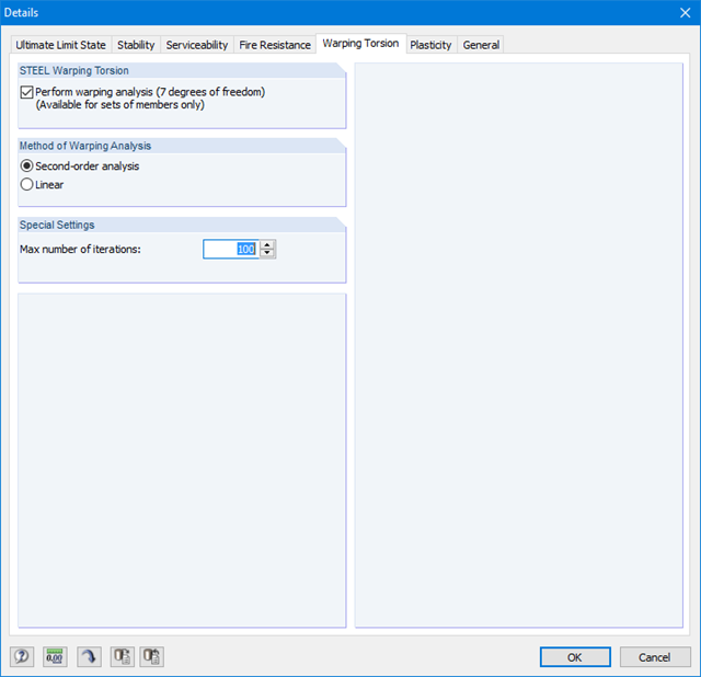
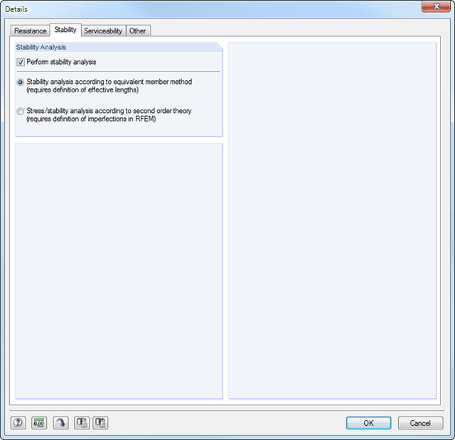
Since RF-/STEEL Warping Torsion is fully integrated in RF-/STEEL AISC and RF‑/STEEL EC3, the data are entered in the same way as for the usual design in these modules. It is only necessary to select the option "Perform warping analysis" in the Details dialog box, tab Warping Torsion (see the figure on the right). You can also define the maximum number of iterations in this dialog box.
The warping torsion analysis is performed for sets of members in RF-/STEEL AISC and RF‑/STEEL EC3. You can define boundary conditions such as nodal supports or member end releases for them.
It is also possible to specify imperfections for the nonlinear calculation.
RF-CONCRETE Surfaces
The nonlinear calculation is activated by selecting the design method of the serviceability limit state. You can individually select the analyses to be performed as well as the stress-strain diagrams for concrete and reinforcing steel. The iteration process can be influenced by these control parameters: convergence accuracy, maximum number of iterations, arrangement of layers over cross-section depth, and damping factor.
You can set the limit values in the serviceability limit state individually for each surface or surface group. Allowable limit values are defined by the maximum deformation, the maximum stresses, or the maximum crack widths. The definition of the maximum deformation requires additional specification as to whether the non-deformed or the deformed system should be used for the design.
RF-CONCRETE Members
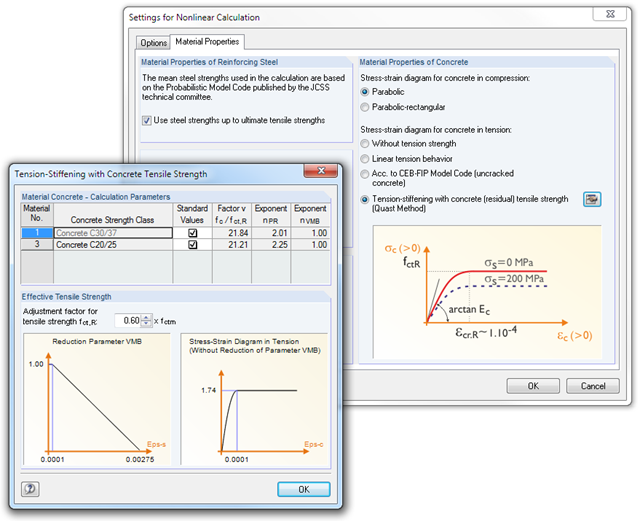
The nonlinear calculation can be applied to the ultimate and the serviceability limit state designs. In addition, you can specify the concrete tensile strength or the tension stiffening between the cracks. The iteration process can be influenced by these control parameters: convergence accuracy, maximum number of iterations, and damping factor.
Before the calculation starts, you should check the input data using the program function. Then, the CONCRETE add‑on module searches the results of relevant load cases, load as well as result combinations. If these cannot be found, RSTAB starts the calculation to determine the required internal forces.
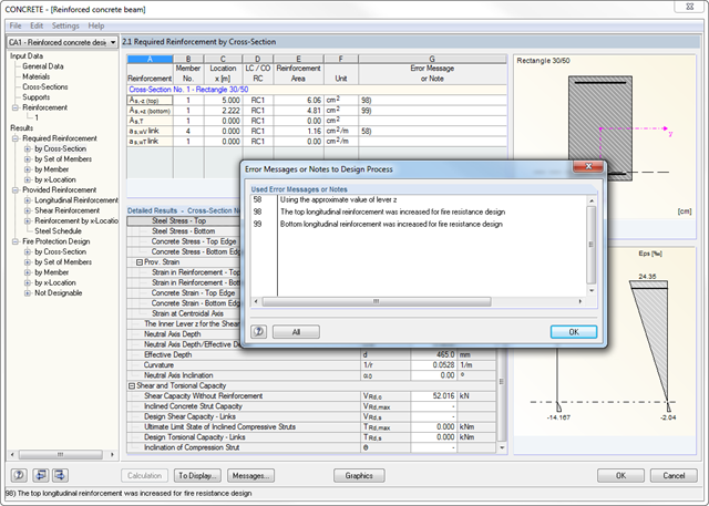
Considering the selected design standard, the required reinforcement areas of the longitudinal and the shear reinforcement as well as the corresponding intermediate results are calculated. If the longitudinal reinforcement determined by the ultimate limit state design is not sufficient for the design of the maximum crack width, it is possible to increase the reinforcement automatically until the defined limit value is reached.
The design of potentially unstable structural components is possible using a nonlinear calculation. According to a respective standard, different approaches are available.
The fire resistance design is performed according to a simplified calculation method in compliance with EN 1992‑1‑2, 4.2. The module uses the zone method mentioned in Annex B2. Furthermore, you can consider the thermal strains in the longitudinal direction and the thermal precamber additionally arising from asymmetrical effects of fire.
The first window shows the maximum design ratios including the corresponding design of each designed load case, load combination, or result combination.
The other result windows list all detailed results sorted by specific subject in extendable tree menus. All intermediate results along the members can be displayed at any location. In this way, you can easily retrace how the module has performed the individual designs.
The complete module data are part of the RFEM/RSTAB printout report. You can select the report contents and extent specifically for the individual designs.
The cross-section resistance design analyzes tension and compression along the grain, bending, bending and tension/compression as well as the strength in shear due to shear force.
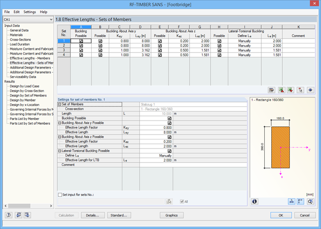
The design of structural components at risk of buckling or lateral buckling is performed according to the Equivalent Member Method and considers the systematic axial compression, bending with and without compression force as well as bending and tension. Deflection of inner spans and cantilevers is compared with the maximum allowable deflection.
Separate design cases allow a flexible analysis for selected members, sets of members, and actions, as well as for the individual stability analyses. such as stability analysis, load duration in case of fire, member slendernesses, and limit deflection can be adjusted as desired.
The cross-section resistance design analyzes tension and compression along the grain, bending, bending and tension/compression as well as the strength in shear due to shear force.
The design of structural components at risk of buckling or lateral buckling is performed according to the Equivalent Member Method and considers the systematic axial compression, bending with and without compression force as well as bending and tension. The deflection of inner spans and cantilevers is compared to the maximum allowable deflection.
Separate design cases allow for a flexible and stability analysis of members, sets of members, and loads.
Design-relevant parameters such as such as stability analysis, load duration in case of fire, member slendernesses, and limit deflection can be adjusted as desired.