3 Wyniki
Wyświetl wyniki:
Sortuj według:
W bieżącym przykładzie walidacyjnym badamy współczynnik parcia wiatru (Cp) płaskiego dachu i ścian za pomocą ASCE7-22 [1]. W rozdziale 28.3 (Obciążenia wiatrem - główny układ odporności na siłę wiatru) i na Rysunku 28.3-1 (przypadek obciążenia 1) znajduje się tabela przedstawiająca wartość Cp dla różnych kątów nachylenia dachu.
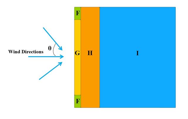
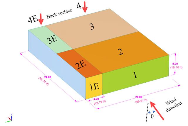
W poniższym przykładzie sprawdzamy wartość ciśnienia wiatru zarówno dla ogólnego projektowania konstrukcyjnego (Cp,10 ), jak i lokalnego projektowania konstrukcyjnego, takiego jak okładziny lub fasady (Cp,1 ) w oparciu o EN 1991-1-4, przykład dachu płaskiego [1] and Baza danych japońskich tuneli aerodynamicznych . Zalecane ustawienie dla trójwymiarowego dachu płaskiego z ostrym okapem zostanie opisane w następnej części.
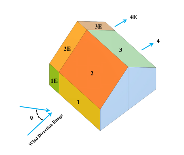
W bieżącym przykładzie walidacyjnym badany jest współczynnik ciśnienia wiatru (Cp) zarówno dla głównych elementów konstrukcyjnych (Cp,ave ), jak i drugorzędnych elementów konstrukcyjnych, takich jak systemy okładziny lub fasady (Cp,local ) w oparciu o NBC 2020 [1] and Baza danych japońskich tuneli aerodynamicznych dla niskiego budynku o nachyleniu 45 stopni. Zalecane ustawienie dla trójwymiarowego dachu płaskiego z ostrym okapem zostanie opisane w następnej części.