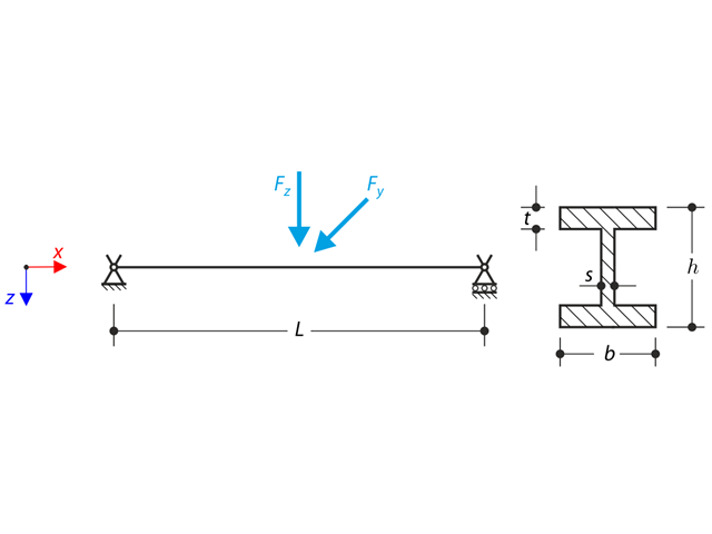
Konstrukcja z profilu I jest osadzona w podporach widłowych. The axial rotation is restricted on both ends while warping is enabled. The structure is loaded by two transverse forces in the middle. The verification example is based on the example introduced by Gensichen and Lumpe.
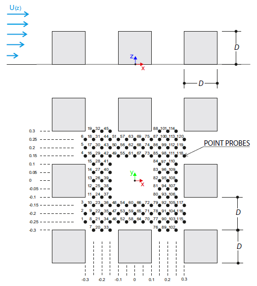
Przykład obliczeniowy opisuje obciążenia wiatrem działające na model grupy budynków w kilku kierunkach. The model consists of eight cubes. The velocity fields obtained by the RWIND simulation are compared with the measured values from the experiment. The experimental data are measured using a thermistor anemometer in the wind tunnel.
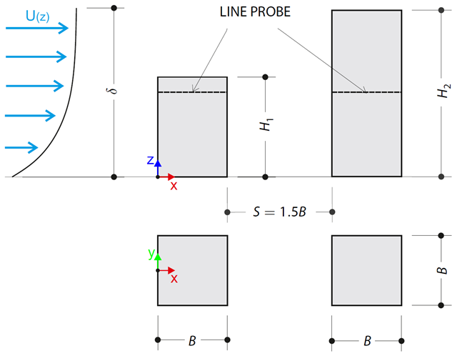
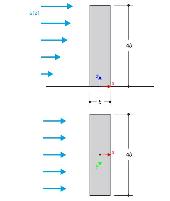
Przykład obliczeniowy opisuje obciążenia od ściskania ścian budynków w układzie tandem, zlokalizowanych w poziomie terenu. The buildings are simplified to rectangular objects and scaled down while maintaining the elevation ratios. The pressure distribution on the walls of the model of a medium-high building was conducted by an experiment. The chosen results (pressure coefficient Cp) are compared with the measured values.
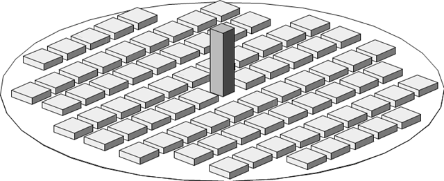
Przykład obliczeniowy opisuje stacjonarny przepływ wokół wieżowca w postaci bloków miejskich (model w skali). The example is given by the Architectural Institute of Japan (AIJ). The chosen results (velocity magnitude) are compared with the measured values.
Przykład obliczeniowy opisuje stacjonarny przepływ wokół izolowanego budynku (model w skali). The chosen results (velocity magnitude) are compared with the measured values.
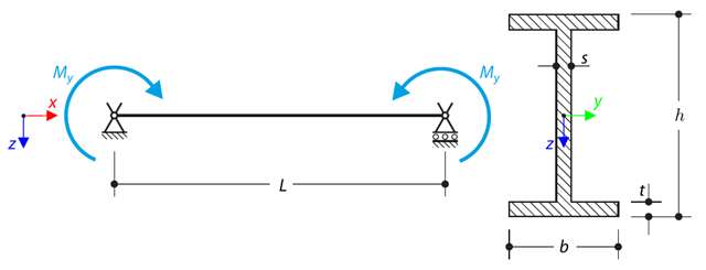
Belka swobodnie podparta jest obciążana przez czyste zginanie. Determine the critical load and corresponding load factor due to lateral buckling.
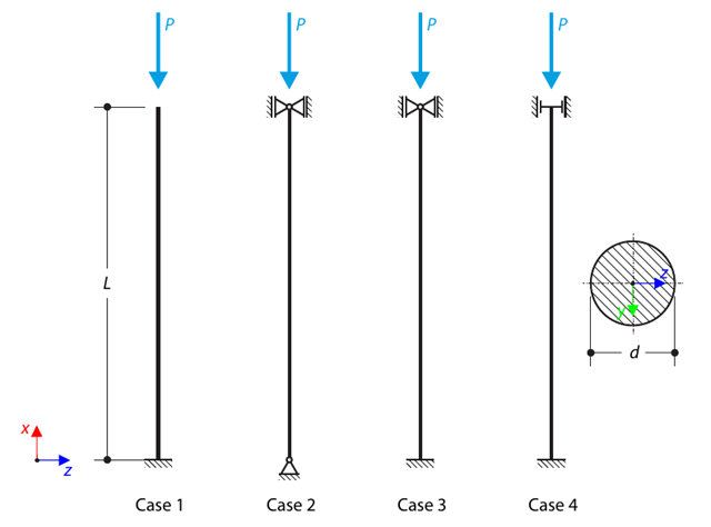
Krzyżulec o przekroju okrągłym jest podparty zgodnie z czterema podstawowymi przypadkami wyboczenia Eulera i poddany działaniu siły ściskającej. Determine the critical load.
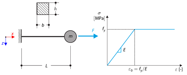
Poniższy przykład obliczeniowy jest oparty na przykładzie obliczeniowym 0122. A single-mass system without damping is subjected to an axial loading force. An ideal elastic-plastic material with characteristics is assumed. Determine the time course of the end-point deflection, velocity, and acceleration.
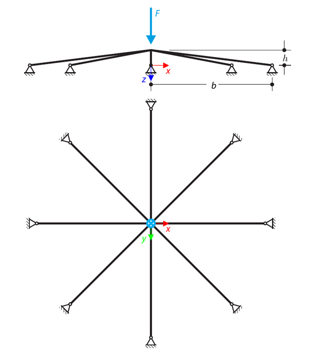
Symetryczna płytka konstrukcja składa się z ośmiu równych prętów kratownicowych, osadzonych w podporach przegubowych. The structure is loaded by a concentrated force and alternatively by imposed nodal deformation over the critical limit point when the snap-through occurs. Imposed nodal deformation is used in RFEM 5 and RSTAB 8 to obtain the full equilibrium path of the snap-through. The self-weight is neglected in this example. Determine the relationship between the actual loading force and the deflection, considering large deformation analysis. Evaluate the load factor at the given deflections.
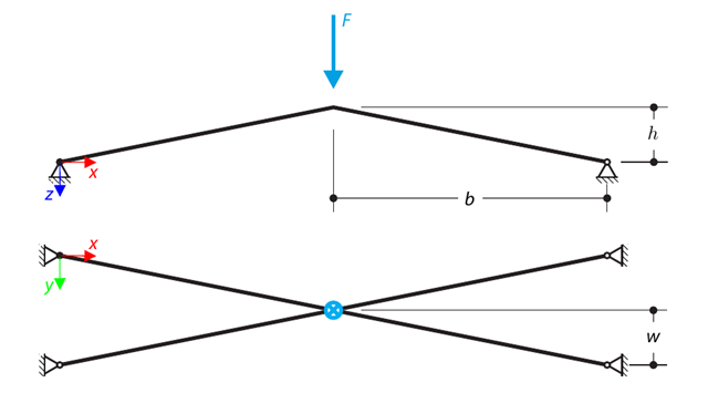
Konstrukcja składa się z czterech prętów kratownicowych, osadzonych w podporach przegubowych. The structure is loaded by a concentrated force and alternatively by imposed nodal deformation over the critical limit point, when snap-through occurs. Imposed nodal deformation is used in RFEM 5 and RSTAB 8 to obtain the full equilibrium path of the snap-through. The self-weight is neglected in this example. Determine the relationship between the actual loading force and the deflection, considering large deformation analysis. Evaluate the load factor at given deflections.