Analiza słupów drewnianych
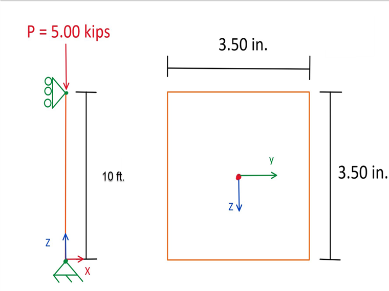
Zostaje zaprojektowany słup o długości 3 m swobodnie podparty nominalnie 89 mm ⋅ 89 mm daglezja-modrzew (DF-L SS) i obciążeniu osiowym 5,00 kips. Celem tej analizy jest określenie skorygowanych współczynników ściskania i nośności słupa na ściskanie. Zakłada się tu standardowy czas trwania obciążenia. Na potrzeby niniejszej analizy kryteria obciążenia zostały uproszczone. Typowe kombinacje obciążeń można znaleźć w sek. 5.2.4 [1]. Na rysunku 01 pokazano wykres prostego słupa z obciążeniami i wymiarami.
Właściwości słupa
Przekrój zastosowany w tym przykładzie to element drewniany o wymiarach nominalnych 89 mm ⋅ 89 mm. Aktualne obliczenia właściwości przekroju słupa z tarcicy można zobaczyć poniżej:
b = 3,50 in, d = 3,50 in, L = 10 ft
- Powierzchnia przekroju brutto:
- Moment statyczny przekroju:
- Moment bezwładności przekroju:
Materiałem zastosowanym w tym przykładzie jest DF-L SS. Właściwości materiału są następujące:
- Referencyjna wartość obliczeniowa na ściskanie: fc = 2 001,52 psi
- Moduł sprężystości E = 1 740 450,00 psi
Współczynniki modyfikacji słupów
W przypadku wymiarowania prętów drewnianych zgodnie z normą CSA O86-19, współczynniki modyfikujące należy zastosować do referencyjnej wartości obliczeniowej nośności na ściskanie (fc ). To z kolei daje skorygowaną wartość obliczeniowej wytrzymałości na ściskanie (Fc ).
Poniżej objaśniono i szczegółowo zdefiniowano każdy ze współczynników korekcyjnych.
KD
Współczynnik czasu trwania obciążenia uwzględnia różne okresy obciążenia. Obciążenia śniegiem, wiatrem i trzęsieniem ziemi są uwzględniane wKD. Oznacza to, że KD zależy od przypadku obciążenia. W tym przypadku KD jest ustawione na 0,65 zgodnie z Tabelą 5.3.2.2 [1] przy założeniu długotrwałego trwania obciążenia.
KSE
Współczynnik użytkowania w warunkach mokrych uwzględnia warunki użytkowania na sucho lub mokro tarcicy oraz wymiary przekroju. W tym przykładzie zakładamy ściskanie w ekstremalnych włóknach i mokre warunki użytkowania. Na podstawie tabeli 6.4.2 [1], Ks wynosi 0,84.
KT
Współczynnik korygujący impregnację uwzględnia drewno impregnowane środkami ogniochronnymi lub innymi środkami chemicznymi zmniejszającymi wytrzymałość. Współczynnik ten jest określany na podstawie wytrzymałości i sztywności w oparciu o udokumentowany test czasu badania, temperatury i wilgotności. Dla tego współczynnika, ust. 6.4.3 Przywołuje się [1]. W tym przykładzie, jeżeli założone są mokre warunki otoczenia, moduł sprężystości mnożony jest przez 0,95 a pozostałe własności przez 0,85.
KZc
Współczynnik rozmiaru uwzględnia różne rozmiary drewna oraz sposób przyłożenia obciążenia do słupa. Więcej informacji na temat tego współczynnika można znaleźć w rozdz. 6.4.5 [1]. Tabela 6.4.5 [[#Refer [1]]] dla tego przykładu, KZ wynosi 1,30.
KH
Współczynnik konstrukcyjny uwzględnia pręty drewniane, które składają się z trzech lub więcej równoległych prętów. Części te nie mogą być oddalone od siebie o więcej niż 610 mm oraz muszą przenosić obciążenie łącznie. Kryterium to jest zdefiniowane jako przypadek 1 w rozdz. 6.4.4 [1]. W tym przykładzie, zgodnie z tabelą 6.4.4, KH wynosi 1,10, ponieważ zakładamy, że jest to pręt ściskany i przypadek 1.
KL
Współczynnik stateczności bocznej uwzględnia podpory boczne na długości pręta, które pomagają zapobiegać przemieszczeniom i obrotom bocznym. Współczynnik przechyłu (KL) oblicza się poniżej.
Ksc
Określoną wytrzymałość tarcicy należy pomnożyć przez współczynnik warunków użytkowania (Ksc ). Współczynnik ten jest określany w odniesieniu do tabeli 6.10 [1].
Obliczeniowa wytrzymałość na ściskanie (FC )
Obliczeniowa wytrzymałość na ściskanie (Fc ) jest określona w poniższym rozdziale. Fc jest obliczana poprzez pomnożenie określonej wytrzymałości na ściskanie (fc ) przez następujące współczynniki modyfikacji.
- KD = 1,00
- KH = 1,00
- KSE = 1,00
- KT = 1,00
Możemy teraz obliczyć Fc korzystając z poniższego równania z Sec. 6.5.4.1 [1].
Współczynnik stateczności bocznej, KC
Współczynnik smukłości (KC ) jest obliczany na podstawie Sec. 6.5.5.2.5 [1]. Przed obliczeniem KC należy najpierw obliczyć obliczeniowy moduł sprężystości dla wymiarowania prętów ściskanych (E05 ). Najpierw należy obliczyć współczynnik rozmiaru dla ściskania dla tarcicy i dla CLT (KZc ) w odniesieniu do Sec. 6.5.5.2.4 [1].
Następnie należy obliczyć współczynnik smukłości dla prętów ściskanych (Cc ) na podstawie Sec. 6.5.5.2.2 [1].
Następnie należy określić obliczeniowy moduł sprężystości dla prętów ściskanych (E05 ) na podstawie Tabeli 6.7 [[#Refer [1]]].
E05 = 8 000 MPa = 1 160 302 psi
Teraz, gdy wszystkie wymagane zmienne zostały obliczone i określone, można obliczyć KC.
Kryterium obliczeniowe dla słupa
Głównym celem tego przykładu jest określenie stopnia wykorzystania dla słupa. W ten sposób można zweryfikować czy rozmiar przekroju pręta jest odpowiedni dla określonego obciążenia lub czy możliwa jest dalsza optymalizacja. Do obliczenia stopnia wykorzystania wymagana jest obliczeniowa nośność na ściskanie równolegle do włókien (Pr ) oraz obliczeniowe obciążenie osiowe przy ściskaniu (Pf ).
Maksymalne osiowe obciążenie ściskające (Pf ) wynosi 5,00 kN.
Następnie na podstawie Sec można obliczyć obliczeniową nośność na ściskanie (Pr ). 6.5.4.1 [1].
Wreszcie można obliczyć stopień wykorzystania (η).
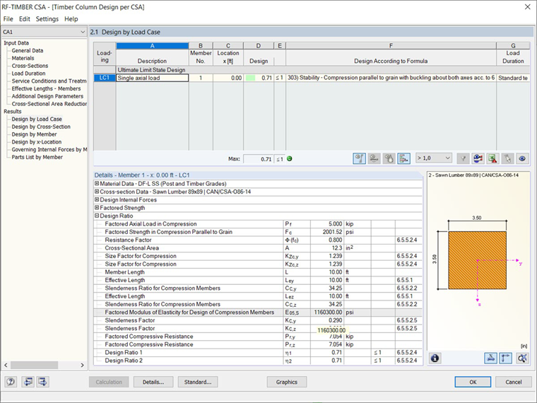
Zastosowanie w RFEM
W przypadku wymiarowania drewna zgodnie z normą CSA O86-19 [1] w RFEM, moduł dodatkowy RF-TIMBER CSA analizuje i optymalizuje przekroje w oparciu o kryteria obciążenia i nośność prętów dla pojedynczego pręta lub zbioru prętów. Podczas modelowania i wymiarowania słupa w powyższym przykładzie w RF-TIMBER CSA, wyniki można porównać.
W tabeli Dane ogólne modułu dodatkowego RF-TIMBER CSA można wybrać pręty, warunki obciążenia i metody obliczeniowe. Materiał i przekroje są definiowane z programu RFEM, a czas trwania obciążenia jest ustawiony na element standardowy. Warunek wilgotności jest ustawiony na „Suche” a zabezpieczenie na „Brak” lub „Zabezpieczenie” (nie nacinane). Współczynnik smukłości KC jest obliczany na podstawie Sec. 6.5.5.2.5 [1]. Z obliczeń modułu wynika, że obliczeniowe obciążenie osiowe przy ściskaniu (Pf ) wynosi 5,00 kN, a obliczeniowa nośność na ściskanie wzdłuż włókien (Pr ) wynosi 7,05 kN. Na podstawie tych wartości obliczany jest stopień wykorzystania (η) wynoszący 0,71, co jest zgodne z ręcznymi obliczeniami analitycznymi przedstawionymi powyżej.