


Timber Column Analysis
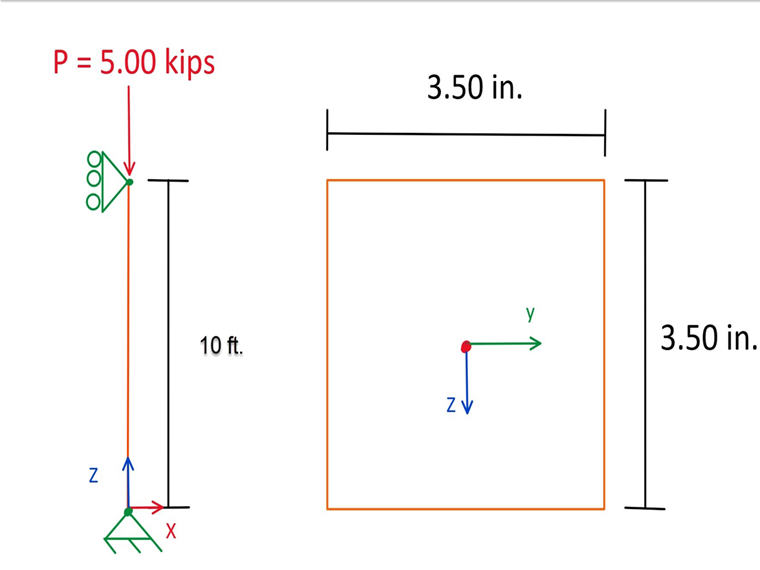
A simply supported 10-foot-long, nominal 89 mm ⋅ 89 mm Douglas Fir-Larch Structural (DF-L SS) column with an axial load of 5.00 kips will be designed. The goal of this analysis is to determine the adjusted compressive factors and compressive resistance of the column. A standard term load duration is assumed. Loading criteria are simplified for this example. Typical load combinations can be referenced in Sec. 5.2.4 [1]. In Image 01, a diagram of the simple column with loads and dimensions is shown.
Column Properties
The cross-section used in this example is a 89 mm ⋅ 89 mm nominal dimension lumber. The actual cross-section property calculations of the sawn timber column can be viewed below:
b = 3.50 in, d = 3.50 in, L = 10 ft
- Gross cross-section area:
- Section modulus:
- Moment of inertia:
The material that will be used for this example is DF-L SS. The material properties are as follows.
- Reference compressive design value: fc = 2,001.52 psi
- Modulus of elasticity: E = 1,740,450.00 psi
Column Modification Factors
For the design of timber members as per the CSA O86-19 standard, modification factors must be applied to the reference compressive design value (fc). This will ultimately provide the adjusted compressive design value (Fc).
Below, each modification factor is further explained and determined for this example.
KD
The load duration factor accounts for different load periods. Snow, wind, and earthquake loads are considered with KD. This means KD is dependent on the load case. In this case, KD is set to 0.65 as per Table 5.3.2.2 [1] assuming a long-term load duration.
KSE
The wet service factor considers dry or wet service conditions on sawn lumber as well as cross-section dimensions. For this example, we are assuming compression at the extreme fiber and wet service conditions. Based on Table 6.4.2 [1], Ks is equal to 0.84.
KT
The treatment adjustment factor considers wood that has been treated with fire-retardant or other strength-reducing chemicals. This factor is determined from strength and stiffness capacities based on documented time, temperature, and moisture test. For this factor, Sec. 6.4.3 [1] is referenced. For this example, 0.95 is multiplied by the modulus of elasticity and 0.85 for all other properties when assuming wet service conditions.
KZc
The size factor considers varying sizes of lumber and how the loading is applied to the column. More info on this factor can be found in Sec. 6.4.5 [1]. For this example, KZ is equal to 1.30 based on dimensions, compression and shear, and Table 6.4.5 [[#Refer [1]]].
KH
The system factor takes into account sawn lumber members that consist of three or more essentially parallel members. These members cannot be spaced more than 610 mm apart and mutually support the load. This criteria is defined as Case 1 in Sec. 6.4.4 [1]. For this example, KH is equal to 1.10 using Table 6.4.4 because we assume it as a compression member and Case 1.
KL
The lateral stability factor considers lateral supports provided along the member length which help prevent lateral displacement and rotation. The lateral stability factor (KL) is calculated below.
Ksc
The specified strength of lumber shall be multiplied by a service-condition factor (Ksc). This factor is determined with reference to Table 6.10 [1].
Factored Specified Strength in Compression (FC)
The factored specified strength in compression (Fc) is determined in the section below. Fc is calculated by multiplying the specified strength for compression (fc) by the following modification factors.
- KD = 1.00
- KH = 1.00
- KSE = 1.00
- KT = 1.00
We can now calculate Fc by using the following equation from Sec. 6.5.4.1 [1].
Lateral Stability Factor, KC
The slenderness factor (KC) is calculated from Sec. 6.5.5.2.5 [1]. Before KC can be calculated, the factored modulus of elasticity for design of compression members (E05) must be calculated. First, the size factor for compression for sawn lumber and for CLT (KZc) must be calculated with reference to Sec. 6.5.5.2.4 [1].
Then, the slenderness ratio for compression members (Cc) must be calculated on the basis of Sec. 6.5.5.2.2 [1].
Next, the factored modulus of elasticity for compression members (E05) needs to be determined on the basis of Table 6.7 [[#Refer [1]]].
E05 = 8,000 MPa = 1,160,302 psi
Now that all of the variables required are calculated and determined, KC can be calculated.
Column Design Ratio
The ultimate goal of this example is to obtain the design ratio for this simple column. This will determine if the member size is adequate under the given load or if it should be further optimized. Calculating the design ratio requires the factored compressive resistance parallel to grain (Pr) and factored axial load in compression (Pf).
The maximum axial compression load (Pf) applied is equal to 5.00 kips.
Next, the factored compressive resistance (Pr) can be calculated from Sec. 6.5.4.1 [1].
Finally, the design ratio (η) can now be calculated.
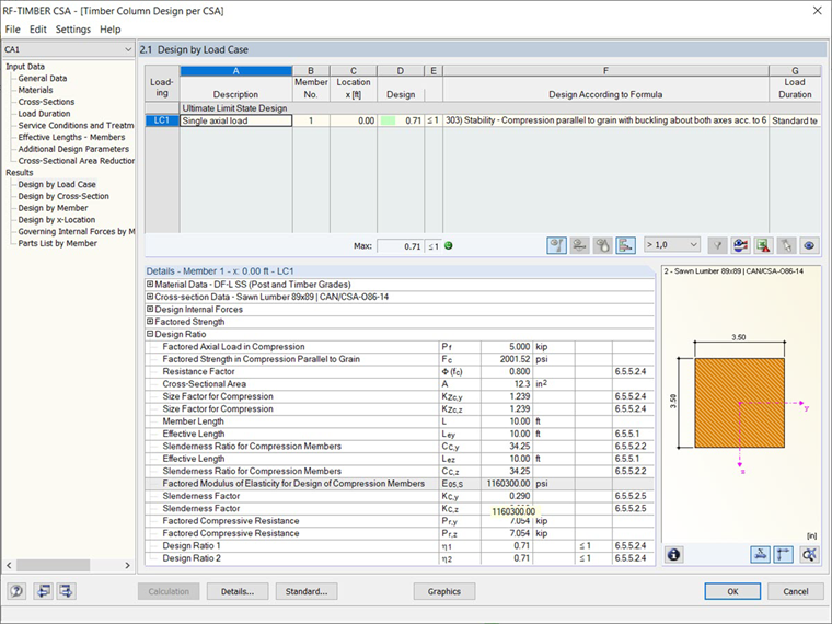
Application in RFEM
For timber design as per the CSA O86-19 [1] standard in RFEM, the add-on module RF-TIMBER CSA analyzes and optimizes cross-sections based on loading criteria and member capacity for a single member or set of members. When modeling and designing the column example above in RF-TIMBER CSA, the results can be compared.
In the General Data table of the RF-TIMBER CSA add-on module, the member, loading conditions, and design methods are selected. The material and cross-sections are defined from RFEM and the load duration is set to standard term. The moisture service condition is set to dry and treatment is set to none or preservative (not incised). The slenderness factor KC is calculated on the basis of Sec. 6.5.5.2.5 [1]. The module calculations produce a factored axial load in compression (Pf) of 5.00 kip and a factored compressive resistance parallel to grain (Pr) of 7.05 kips. A design ratio (η) of 0.71 is determined from these values aligning well with the analytical hand calculations shown above.
.png?mw=760&hash=00e603e774c25d66a799f2fb751ca6a37e0f1b75)