Program RFEM 6 do analizy statyczno-wytrzymałościowej jest podstawą systemu modułowego. Program główny RFEM 6 służy do definiowania konstrukcji, materiałów i obciążeń płaskich i przestrzennych układów konstrukcyjnych składających się z płyt, ścian, powłok i prętów. Program umożliwia również tworzenie konstrukcji mieszanych oraz modelowanie elementów bryłowych i kontaktowych.
RSTAB 9 to wydajne oprogramowanie do obliczeń konstrukcji szkieletowych 3D, odzwierciedlające aktualny stan wiedzy i pomagające inżynierom sprostać wymaganiom współczesnej inżynierii lądowej.
Często zbyt długo zajmujesz się obliczaniem przekrojów? Oprogramowanie firmy Dlubal i program samodzielny RSECTION ułatwiają pracę, określając i przeprowadzając analizę naprężeń dla różnych przekrojów.
Czy zawsze wiesz, skąd wieje wiatr? Oczywiście od strony innowacji! RWIND 3 to program, który wykorzystuje cyfrowy tunel aerodynamiczny do numerycznej symulacji przepływu wiatru. Program symuluje przepływ wokół dowolnej geometrii budynku i określa obciążenia wiatrem na powierzchnie.
Szukasz narzędzia do przeglądu stref obciążenia śniegiem, wiatrem i trzęsieniem ziemi? Dobrze trafiłeś! Skorzystaj z narzędzia do geolokalizacji do szybkiego i skutecznego definiowania obciążenia śniegiem, prędkości wiatru, obciążenia trzęsieniem ziemi, zgodnie z Eurokodem i innymi międzynarodowymi normami.
Chcesz wypróbować możliwości programów Dlubal Software? To Twoja szansa! Dzięki 90-dniowej pełnej wersji, możesz w pełni przetestować wszystkie nasze programy.
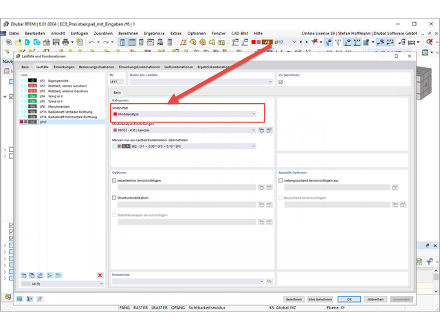
Aby wyświetlić kształty drgań własnych w analizie dynamicznej, należy utworzyć przypadek obciążenia typu Analiza modalna i określić w nim ustawienia dla analizy modalnej.
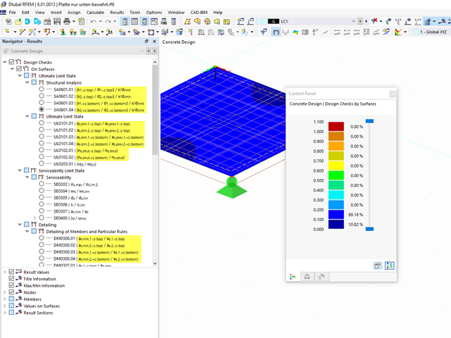
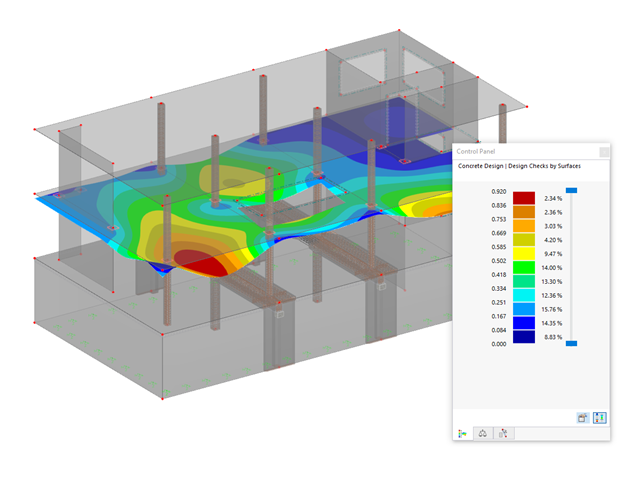
Po zakończeniu obliczeń można ocenić uzyskane wyniki w nawigatorze Wyniki. W tabeli można również znaleźć dalsze informacje.
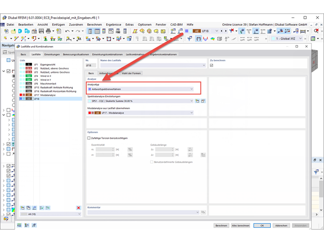
Aby przeprowadzić analizę trzęsienia ziemi, potrzebna jest analiza modalna, a następnie przypadek obciążenia typu Analiza spektrum odpowiedzi.
Po przeprowadzeniu analizy modalnej należy utworzyć nowy przypadek obciążenia. Tutaj znajdują się zwykłe ustawienia z poprzedniej generacji programu.
W zakładce Spektrum odpowiedzi można zdefiniować swoje spektrum odpowiedzi w zwykły sposób. Jeżeli chcesz użyć spektrum odpowiedzi zgodnie z normą, upewnij się, że w danych ogólnych normy II wybrano żądaną normę.
W zakładce Wybór trybów można wybrać kształty postaci i w razie potrzeby przefiltrować je.
Po obliczeniu przypadku obciążenia otrzymujemy wyniki.
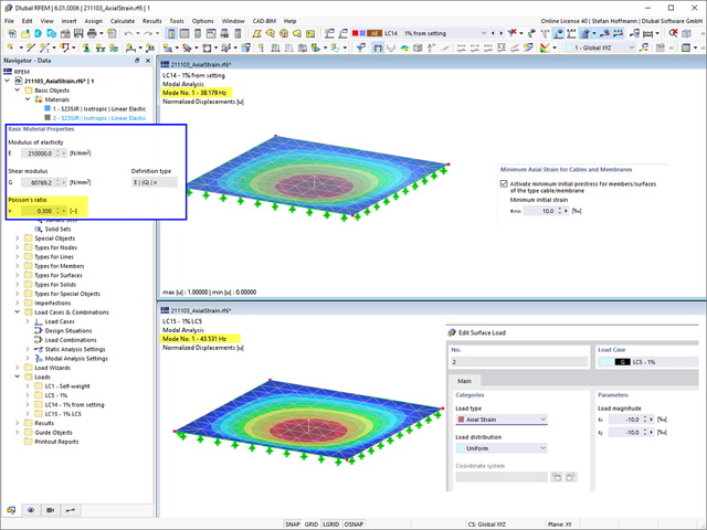
W ustawieniach analizy modalnej można ustawić minimalne odkształcenie osiowe dla kabli i membran, aby zastosować początkowe naprężenie wstępne dla obiektów, a tym samym poprawić zbieżność obliczeń. Wstępne naprężenie wstępne jest stosowane do obiektów w sposób uproszczony.
Porównując to ustawienie z obciążeniem powierzchniowym typu Odkształcenie osiowe, należy zwrócić uwagę na fakt, że te dwa podejścia różnią się od siebie. Przy obciążeniu powierzchniowym przeprowadza się obliczenia w taki sposób, że rzeczywiste naprężenie może odbiegać od zadanego. Obliczenia uwzględniają również inne warunki brzegowe, takie jak współczynnik Poissona materiału.
Można to łatwo sprawdzić, zmieniając współczynnik Poissona w materiale. Stosunek Poissona ' s różny od 0 oznacza, że odkształcenie w kierunku x i y powierzchni oddziałuje ze sobą, co nie prowadzi już do stałego naprężenia/odkształcenia na całej powierzchni.
Jeżeli współczynnik Poissona wynosi 0, można uzyskać takie same wyniki.
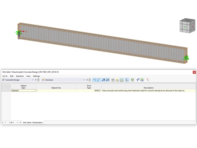
Należy sprawdzić, czy materiał przypisany do prętów jest zgodny z normą wybraną do obliczeń w dodatku „Wymiarowanie betonu”.
Ponadto należy sprawdzić, czy wszystkie właściwości obliczeniowe (klasa wytrzymałości, otulina betonowa, zbrojenie na ścinanie i podłużne itp.) zostały prawidłowo określone w oknie dialogowym „Edytować pręt”.
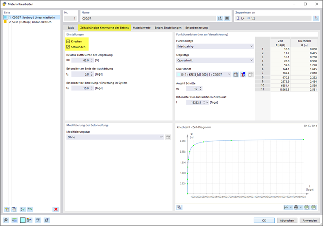
Uwzględnianie pełzania i/lub skurczu przy wymiarowaniu betonu można aktywować w oknie dialogowym Edytować materiał (patrz rys. 01).
Po aktywowaniu dla materiału pełzania lub skurczu w oknach dialogowych Przekroje i Grubości , w których stosowany jest ten materiał, dostępna jest opcja "Właściwości betonu zależne od czasu". Zaznacz to pole wyboru, a następnie zdefiniuj parametry dla pełzania lub skurczu w odpowiedniej zakładce (patrz Rysunek 02).
Więcej informacji można znaleźć w rozdziale instrukcji online dotyczącej wymiarowania betonu, klikając poniższy link.
Nie, nie jest to możliwe w obecnym stanie rozwoju programu RFEM 6.
Patrz także najczęściej zadawane pytania dotyczące programów RFEM 5 i RF-CONCRETE Surfaces pod linkiem poniżej.Koncepcja obliczeniowa ma obecnie podobną strukturę i opiera się na zbrojeniu górnej i dolnej części.
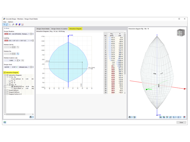
Aby wyświetlić wykres interakcji, otwórz okno dialogowe "Szczegóły obliczeń" Wymiarowania betonu.
W lewej części okna dialogowego można wybrać „Diagram interakcji”. Tym samym pojawia się dodatkowa zakładka „Wykres interakcji”. Tutaj można kontrolować ustawienia wyświetlania wyników.
Tak, analiza odkształceń uwzględniająca stan zarysowany przekroju jest uwzględniona przy wymiarowaniu betonu w programie RFEM 6.
W tym celu dla każdego elementu w obliczeniach betonu obliczana jest sztywność efektywna zgodnie z istniejącym stanem przekroju - zarysowanym (stan II) lub niezarysowanym (stan I), a następnie wykorzystana w drugich obliczeniach MES dla odkształcenia.
W programie RFEM 5 odpowiada to rozwiązaniu w module dodatkowym "RF-CONCRETE Deflect". W programie RFEM 6 metoda ta jest uwzględniona w wymiarowaniu betonu.
W artykule technicznym pod tym linkiem można znaleźć więcej informacji na temat określania stanu zarysowania w ramach analizy odkształceń.
Masy można pominąć w ustawieniach analizy modalnej.
Możliwe jest pominięcie mas we wszystkich nieruchomych podporach węzłowych i podporach liniowych lub utworzenie wyboru z poszczególnych obiektów.
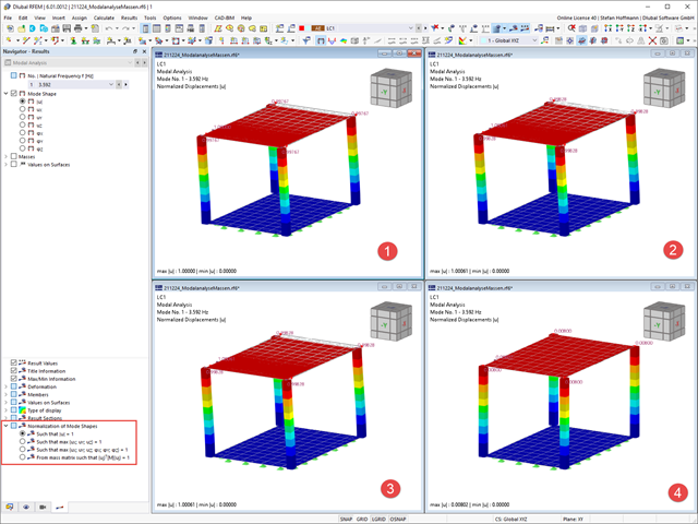
Bezpośrednio w nawigatorze Wyniki można dostosować wyświetlanie normalizacji postaci drgań własnych. W przypadku zmiany ustawienia nie jest konieczne ponowne obliczanie.
W zależności od ustawienia największe przemieszczenie lub odkształcenie stanowi wartość odniesienia 1, do której skalowane są pozostałe wyniki.