Program RFEM 6 do analizy statyczno-wytrzymałościowej jest podstawą systemu modułowego. Program główny RFEM 6 służy do definiowania konstrukcji, materiałów i obciążeń płaskich i przestrzennych układów konstrukcyjnych składających się z płyt, ścian, powłok i prętów. Program umożliwia również tworzenie konstrukcji mieszanych oraz modelowanie elementów bryłowych i kontaktowych.
RSTAB 9 to wydajne oprogramowanie do obliczeń konstrukcji szkieletowych 3D, odzwierciedlające aktualny stan wiedzy i pomagające inżynierom sprostać wymaganiom współczesnej inżynierii lądowej.
Często zbyt długo zajmujesz się obliczaniem przekrojów? Oprogramowanie firmy Dlubal i program samodzielny RSECTION ułatwiają pracę, określając i przeprowadzając analizę naprężeń dla różnych przekrojów.
Czy zawsze wiesz, skąd wieje wiatr? Oczywiście od strony innowacji! RWIND 3 to program, który wykorzystuje cyfrowy tunel aerodynamiczny do numerycznej symulacji przepływu wiatru. Program symuluje przepływ wokół dowolnej geometrii budynku i określa obciążenia wiatrem na powierzchnie.
Szukasz narzędzia do przeglądu stref obciążenia śniegiem, wiatrem i trzęsieniem ziemi? Dobrze trafiłeś! Skorzystaj z narzędzia do geolokalizacji do szybkiego i skutecznego definiowania obciążenia śniegiem, prędkości wiatru, obciążenia trzęsieniem ziemi, zgodnie z Eurokodem i innymi międzynarodowymi normami.
Chcesz wypróbować możliwości programów Dlubal Software? To Twoja szansa! Dzięki 90-dniowej pełnej wersji, możesz w pełni przetestować wszystkie nasze programy.
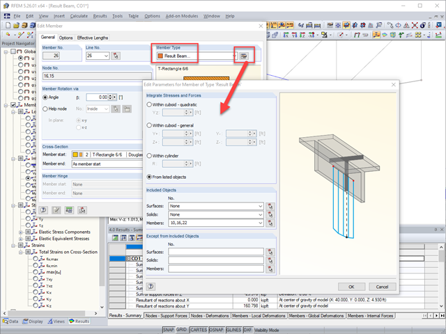
Chociaż siły na końcach prętów są zazwyczaj stosowane do wymiarowania połączeń (patrz FAQ 4918) mogą Państwo zainteresować się sumarycznymi siłami wewnętrznymi w określonym węźle, w którym kilka prętów jest układanych w tym punkcie pod różnymi kątami. . Program domyślnie nie podaje informacji o wynikach sił wewnętrznych w węzłach.
Najlepszym rozwiązaniem jest utworzenie belki wynikowej, gdzie można wybrać pręty, które mają zostać uwzględnione podczas dodawania sił wewnętrznych. Belki wynikowe nie zwiększają sztywności modelu i są używane wyłącznie jako narzędzie do interpretacji wyników (patrz link poniżej KB 1406). Siły wewnętrzne na belkach wynikowych można przeglądać tak samo, jak każdy inny pręt, sumowany przez siłę na końcu pręta w określonym węźle.
Należy pamiętać, że belki wynikowe tworzą od wewnątrz płaszczyznę prostopadłą w każdym punkcie wzdłuż i na obu końcach pręta, aby określić, które siły mają zostać uwzględnione w wynikach. Działa to dobrze w przypadku wszystkich elementów, które nie leżą bezpośrednio w płaszczyźnie prostopadłej do belki wynikowej. W przypadku elementów, które są wprost prostopadłe, należy zastosować bardzo niewielkie przesunięcie do elementu, aby nie był już idealnie prostopadły, aby belka wynikowa również mogła objąć jego wyniki.
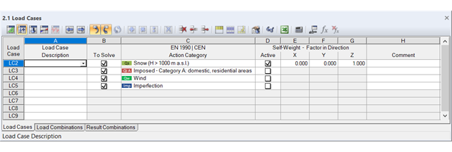
Zazwyczaj jest to potrzebne tylko raz w przypadku obciążenia stałego, w żadnym innym przypadku nie jest możliwe. Każdy dodatkowy przypadek obciążenia należy uwzględnić w kombinacjach obciążeń zazwyczaj miarodajnych przy określaniu sił wewnętrznych.
Program umożliwia aktywację obciążenia własnego dla każdego przypadku obciążenia. Do użytkownika należy decyzja, który przypadek może być zastosowany. Z powodu wspomnianego powyżej ciężar własny jest domyślnie aktywowany tylko dla pierwszego przypadku obciążenia (patrz rysunek 01).
Jeżeli przegroda budynku nie jest zamodelowana, w programie RWIND Simulation obciążenie wiatrem jest przykładane tylko na powierzchnie prętów. Elementy, które rozkładałyby nacisk na pręty, nie istnieją. W takim przypadku funkcja "Zamknij otwory" nie jest odpowiednia do wymiany powierzchni. Z tego względu automatyczne przenoszenie obciążenia wiatrem do programu RFEM lub RSTAB nie jest możliwe.
Można jednak modelować przegrodę budynku w programie RFEM w osobnym modelu i analizować ją w RWIND Simulation. Ciśnienie wiatru można następnie wygenerować ręcznie jako obciążenie, na przykład za pomocą generatorów obciążeń. Zastosowanie funkcji pokazano w filmie.
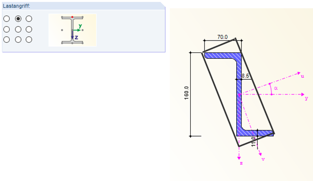
Ustawienie przyłożenia obciążenia określone w Szczegółach odnosi się do osi głównych danego przekroju. Dla przykładowego przekroju Z, wokół przekroju ustawiono prostokąt z dziewięcioma węzłami krawędziowymi. Przyłożenie obciążenia jest wówczas zawsze powiązane z obróconym kątem osi głównej i odpowiednimi mimośrodami.