15 Wyniki
Wyświetl wyniki:
Sortuj według:

W rozszerzeniu Połączenia stalowe można klasyfikować sztywności połączeń.
Oprócz sztywności początkowej w tabeli wyświetlane są również wartości graniczne dla połączeń przegubowych i sztywnych dla wybranych sił wewnętrznych N, My i/lub Mz. Uzyskana klasyfikacja jest następnie wyświetlana w tabeli jako „przegubowa”, „półsztywna” i „sztywna”.
Przejdź do filmu
W rozszerzeniu „Połączenia stalowe” można uwzględnić naprężenie wstępne śrub w obliczeniach dla wszystkich komponentów. Sprężenie można łatwo aktywować za pomocą pola wyboru w parametrach śruby i ma ono wpływ zarówno na analizę naprężeniowo-odkształceniową, jak i na analizę sztywności.
Śruby sprężone to specjalne śruby stosowane w konstrukcjach stalowych w celu wygenerowania dużej siły zaciskowej między połączonymi elementami konstrukcyjnymi. Ta siła docisku powoduje tarcie między elementami konstrukcyjnymi, co umożliwia przenoszenie sił.
Funkcjonalność
Śruby sprężane są dokręcane z określonym momentem, co powoduje ich rozciąganie i powstawanie siły rozciągającej. Ta siła rozciągająca jest przenoszona na połączone elementy i prowadzi do powstania dużej siły mocującej. Siła zaciskowa zapobiega poluzowaniu połączenia i zapewnia niezawodne przenoszenie siły.
Zalety
- Wysoka nośność: Śruby wstępnie rozciągane mogą przenosić duże siły.
- Niskie odkształcenie: Minimalizują odkształcenie połączenia.
- Wytrzymałość zmęczeniowa: Są odporne na zmęczenie.
- Łatwość montażu: Są one stosunkowo łatwe w montażu i demontażu.
Analiza i wymiarowanie
Obliczenia śrub sprężanych są przeprowadzane w RFEM z wykorzystaniem modelu analitycznego ES wygenerowanego przez rozszerzenie "Połączenia stalowe". Uwzględnia ona siłę zwarcia, tarcie między elementami konstrukcyjnymi, wytrzymałość śrub na ścinanie oraz nośność elementów konstrukcyjnych. Wymiarowanie odbywa się zgodnie z DIN EN 1993-1-8 (Eurokod 3) lub amerykańską normą ANSI/AISC 360-16. Utworzony model analityczny wraz z wynikami można zapisać i wykorzystać jako niezależny model w programie RFEM.

Rozszerzenie Połączenia stalowe umożliwia wymiarowanie połączeń prętów o złożonych przekrojach. Ponadto można przeprowadzać obliczenia połączeń dla prawie wszystkich przekrojów cienkościennych z biblioteki programu RFEM.
Przejdź do filmu
W rozszerzeniu Połączenia stalowe można wymiarować połączenia zgodnie z amerykańską normą ANSI/AISC 360-16. Zintegrowane zostały następujące metody obliczeń:
- Obliczenia współczynnika obciążenia i odporności (LRFD)
- Projektowanie dopuszczalnych naprężeń (ASD)
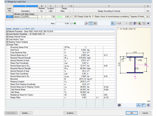
Dzięki zintegrowanemu rozszerzeniu modułu RF-/STEEL Warping Torsion, możliwe jest przeprowadzenie obliczeń zgodnie z Design Guide 9 w RF-/STEEL AISC.
Obliczenia są przeprowadzane z 7 stopniami swobody zgodnie z teorią skręcania skrępowanego i umożliwiają realistyczne obliczenia stateczności z uwzględnieniem skręcania.
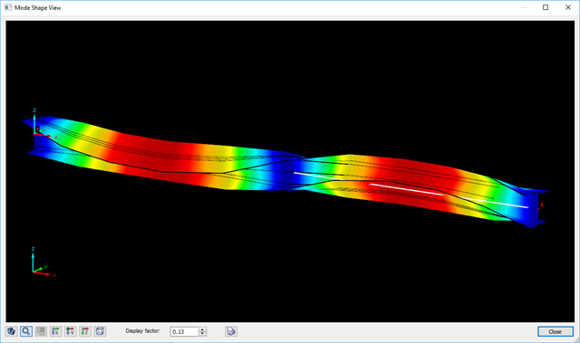
Definiowanie krytycznego momentu wyboczeniowego odbywa się w module RF-/STEEL AISC za pomocą solwera wartości własnych, który umożliwia dokładne określenie krytycznego obciążenia wyboczeniowego.
Solwer wartości własnych pokazuje okno z grafiką wartości własnych, które umożliwia sprawdzenie warunków brzegowych.
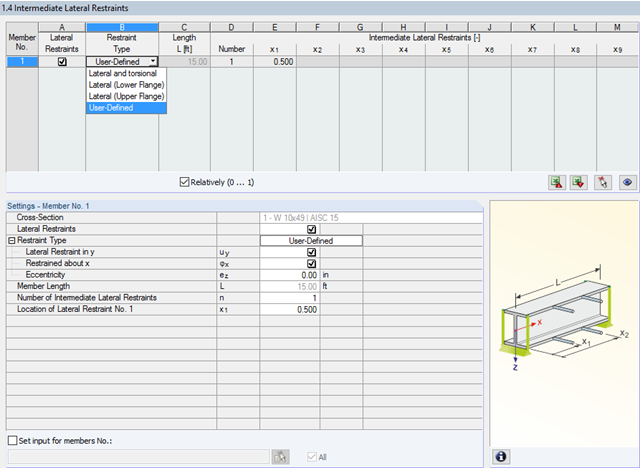
W programie STEEL AISC możliwe jest uwzględnienie pośrednich podpór bocznych w dowolnym miejscu. Na przykład, możliwa jest stabilizacja tylko górnej półki.
Ponadto można przypisać boczne podpory pośrednie zdefiniowane przez użytkownika; na przykład pojedyncze sprężyny obrotowe i sprężyny translacyjne w dowolnym miejscu przekroju.
- Modelowanie przekroju za pomocą elementów, profili, łuków i elementów punktowych
- Biblioteka właściwości materiałów, granic plastyczności i naprężeń granicznych, którą użytkownik może rozbudowywać
- Właściwości przekrojów otwartych, zamkniętych i niepołączonych
- Efektywne właściwości przekrojów wykonanych z różnych materiałów
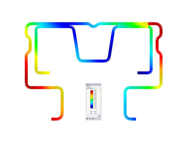
- Określanie naprężeń w spoinach pachwinowych
- Analiza naprężeń wraz z obliczaniem skręcania swobodnego i skrępowanego
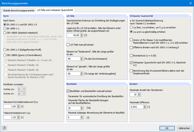
- Sprawdzanie stosunków (c/t)
- Przekroje efektywne według
- EN 1993-1-5 (w tym płyty usztywnione zgodnie z rozdziałem 4.5)
-
 EN 1993-1-3
 -
EN 1999-1-1
-
 DIN 18800-2
- Klasyfikacja według
-
EN 1993-1-1
-
EN 1999-1-1
-
- Interfejs z MS Excel służący do importu i eksportu tabel
- Raport
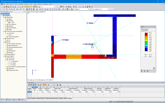
SHAPE-THIN określa wszystkie odpowiednie charakterystyki przekroju, wraz z plastycznymi siłami granicznymi i momentami. Nakładające się powierzchnie są uwzględniane w sposób realistyczny. Dla przekrojów utworzonych z różnych materiałów, SHAPE-THIN określa idealne charakterystyki przekroju w odniesieniu do materiału referencyjnego.
Oprócz analizy naprężeń w stanie sprężystym, można prowadzić również obliczenia w stanie plastycznym, zawierające interakcję sił wewnętrznych dla różnorodnych kształtów przekroju. Obliczenia interakcji plastycznej prowadzane są według metody Simplex. Podczas analizy naprężeń można wybrać różne teorie (Tresca lub von Mises).
SHAPE-THIN przeprowadza klasyfikację przekroju zgodnie z EN 1993-1-1 i EN 1999-1-1. W przypadku przekrojów stalowych o przekroju 4, program określa szerokości efektywne dla płyt usztywnionych lub nieusztywnionych, zgodnie z EN 1993-1-1 i EN 1993-1-5. W przypadku przekrojów aluminiowych o przekroju klasy 4, program oblicza grubości efektywne zgodnie z EN 1999-1-1.
Opcjonalnie SHAPE-THIN sprawdza wartości graniczne c/t zgodnie z metodami obliczeniowymi el-el, el-pl lub pl-pl zgodnie z DIN 18800. Przekrój jest klasyfikowany według danej kombinacji sił wewnętrznych.