14 Wyniki
Wyświetl wyniki:
Sortuj według:
- 002089
- Ogólne informacje
- Skręcanie skrępowane (7 stopni swobody) RFEM 6
- Skręcanie skrępowane (7 stopni swobody) RSTAB 9
- Uwzględnienie 7 lokalnych kierunków deformacji (ux , uy, uz, φx, φy, φz, ω ) lub 8 sił wewnętrznych (N , Vu, Vv, Mt, pri, Mt, s, Mu, Mv, Mω ) przy obliczaniu elementów prętowych
- Możliwość stosowania w połączeniu z analizą statyczno-wytrzymałościową według teorii II rzędu, i analiza dużych deformacji (można również uwzględnić imperfekcje)
- W połączeniu z rozszerzeniem Analiza stateczności umożliwia definiowanie współczynników obciążenia krytycznego i kształtów drgań dla problemów stateczności, takich jak wyboczenie skrętne i zwichrzenie
- Uwzględnianie blach czołowych i usztywnień poprzecznych jako sprężystości skrępowanej podczas obliczania przekrojów dwuteowych z automatycznym określaniem i wyświetlaniem graficznym sztywności sprężystości deplanacyjnej
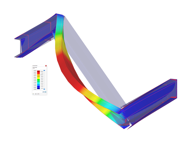
- Graficzne przedstawienie deplanacji przekroju prętów w stanie odkształcenia
- Pełna integracja z RFEM i RSTAB

- 002090
- Ogólne informacje
- Skręcanie skrępowane (7 stopni swobody) RFEM 6
- Skręcanie skrępowane (7 stopni swobody) RSTAB 9
Obliczenia skręcania skrępowanego można przeprowadzić dla całego układu. Uwzględniasz zatem dodatkową wartość 7 stopnia swobody w obliczeniach pręta. Sztywności połączonych elementów konstrukcyjnych są uwzględniane automatycznie. Oznacza to, że nie ma potrzeby' definiowania równoważnych sztywności sprężystych ani warunków podparcia dla układu odłączanego.
Następnie można wykorzystać siły wewnętrzne z obliczeń ze skręcaniem skrępowanym w rozszerzeniu do obliczeń. W zależności od materiału i wybranej normy należy uwzględnić bimoment wyboczeniowy i drugorzędny moment skręcający. Typowym zastosowaniem jest analiza stateczności według teorii drugiego rzędu z wykorzystaniem imperfekcji w konstrukcjach stalowych.
Czy wiecie, że...? Zastosowanie nie ogranicza się do przekrojów stalowych cienkościennych. Pozwala to na przykład na przeprowadzenie obliczeń idealnego momentu krytycznego dla belek o przekrojach z drewna litego.

- 002401
- Ogólne informacje
- Skręcanie skrępowane (7 stopni swobody) RFEM 6
- Skręcanie skrępowane (7 stopni swobody) RSTAB 9
- Funkcję skręcania skrępowanego można aktywować lub dezaktywować w zakładce Rozszerzenia w Danych podstawowych modelu.
- Po aktywowaniu rozszerzenia interfejs użytkownika w programie RFEM zostaje rozszerzony o nowe wpisy w nawigatorze, tabelach i oknach dialogowych.
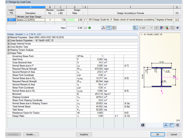
Dzięki zintegrowanemu rozszerzeniu modułu RF-/STEEL Warping Torsion, możliwe jest przeprowadzenie obliczeń zgodnie z Design Guide 9 w RF-/STEEL AISC.
Obliczenia są przeprowadzane z 7 stopniami swobody zgodnie z teorią skręcania skrępowanego i umożliwiają realistyczne obliczenia stateczności z uwzględnieniem skręcania.
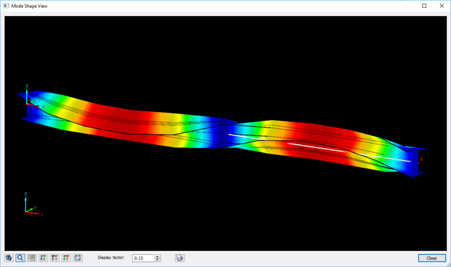
Definiowanie krytycznego momentu wyboczeniowego odbywa się w module RF-/STEEL AISC za pomocą solwera wartości własnych, który umożliwia dokładne określenie krytycznego obciążenia wyboczeniowego.
Solwer wartości własnych pokazuje okno z grafiką wartości własnych, które umożliwia sprawdzenie warunków brzegowych.
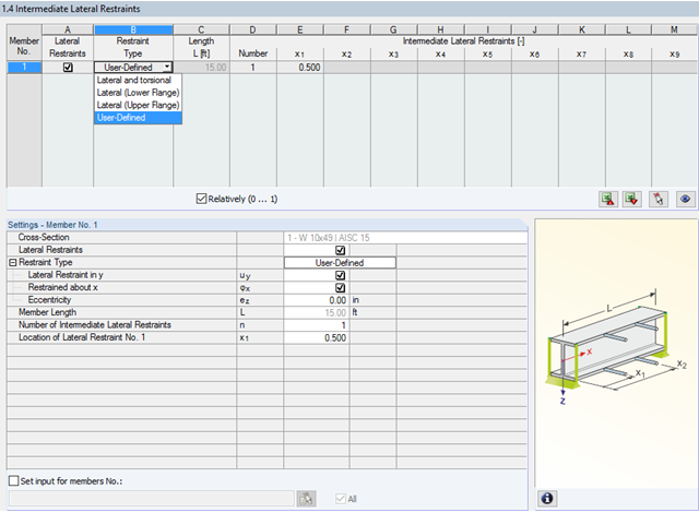
W programie STEEL AISC możliwe jest uwzględnienie pośrednich podpór bocznych w dowolnym miejscu. Na przykład, możliwa jest stabilizacja tylko górnej półki.
Ponadto można przypisać boczne podpory pośrednie zdefiniowane przez użytkownika; na przykład pojedyncze sprężyny obrotowe i sprężyny translacyjne w dowolnym miejscu przekroju.
- Modelowanie przekroju za pomocą elementów, profili, łuków i elementów punktowych
- Biblioteka właściwości materiałów, granic plastyczności i naprężeń granicznych, którą użytkownik może rozbudowywać
- Właściwości przekrojów otwartych, zamkniętych i niepołączonych
- Efektywne właściwości przekrojów wykonanych z różnych materiałów
- Określanie naprężeń w spoinach pachwinowych
- Analiza naprężeń wraz z obliczaniem skręcania swobodnego i skrępowanego
- Sprawdzanie stosunków (c/t)
- Przekroje efektywne według
- EN 1993-1-5 (w tym płyty usztywnione zgodnie z rozdziałem 4.5)
-
 EN 1993-1-3
 -
EN 1999-1-1
-
 DIN 18800-2
- Klasyfikacja według
-
EN 1993-1-1
-
EN 1999-1-1
-
- Interfejs z MS Excel służący do importu i eksportu tabel
- Raport
- Stosuje się do prętów zdefiniowanych jako zbiory prętów
- Oddzielny solwer uwzględniający 7 kierunków deformacji (ux , uy, uz, φx, φy, φz, ω ) lub 8 sił wewnętrznych (N, Vu, Vv, Mt, pri, Mt, s, Mu, Mv,M )
- Projektowanie nieliniowe według analizy drugiego rzędu
- Wprowadzanie imperfekcji
- Obliczanie współczynników obciążenia krytycznego i postaci wyboczenia oraz ich wizualizacja (wraz z skręcaniem skrępowanym)
- Integracja z wymiarowaniem prętów w modułach dodatkowych RF-/STEEL AISC i RF-/STEEL EC3
- Dostępne dla wszystkich przekrojów stalowych cienkościennych
Wszystkie wyniki mogą być wyświetlane i analizowane w postaci numerycznej i graficznej. W przypadku wizualizacji wyników, narzędzia wyboru pozwalają na ich szczegółową ocenę.
Protokół wydruku spełnia wysokie standardy Produkt | RFEM 6 und des Produkt | RSTAB 9 . Modyfikacje przekroju aktualizowane są automatycznie.
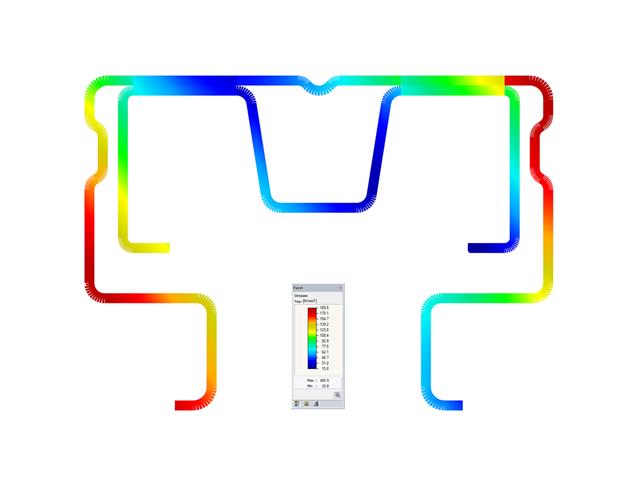
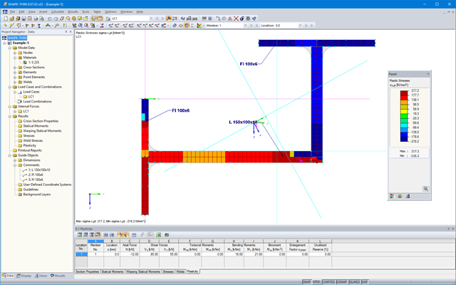
SHAPE-THIN określa wszystkie odpowiednie charakterystyki przekroju, wraz z plastycznymi siłami granicznymi i momentami. Nakładające się powierzchnie są uwzględniane w sposób realistyczny. Dla przekrojów utworzonych z różnych materiałów, SHAPE-THIN określa idealne charakterystyki przekroju w odniesieniu do materiału referencyjnego.
Oprócz analizy naprężeń w stanie sprężystym, można prowadzić również obliczenia w stanie plastycznym, zawierające interakcję sił wewnętrznych dla różnorodnych kształtów przekroju. Obliczenia interakcji plastycznej prowadzane są według metody Simplex. Podczas analizy naprężeń można wybrać różne teorie (Tresca lub von Mises).
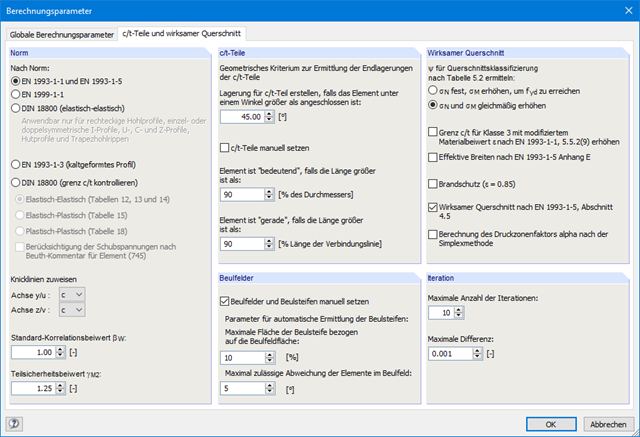
SHAPE-THIN przeprowadza klasyfikację przekroju zgodnie z EN 1993-1-1 i EN 1999-1-1. W przypadku przekrojów stalowych o przekroju 4, program określa szerokości efektywne dla płyt usztywnionych lub nieusztywnionych, zgodnie z EN 1993-1-1 i EN 1993-1-5. W przypadku przekrojów aluminiowych o przekroju klasy 4, program oblicza grubości efektywne zgodnie z EN 1999-1-1.
Opcjonalnie SHAPE-THIN sprawdza wartości graniczne c/t zgodnie z metodami obliczeniowymi el-el, el-pl lub pl-pl zgodnie z DIN 18800. Przekrój jest klasyfikowany według danej kombinacji sił wewnętrznych.