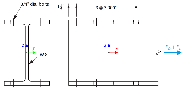
Prut s W-profilem podle ASTM A992 je vybrán tak, aby unesl vlastní tíhu 30 000 kips a užitné zatížení 90 000 kips v tahu. Ověřte pevnost prutu pomocí LRFD a ASD.
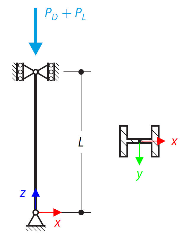
Sloup s profilem ASTM A992 14×132 W je zatížen danými osovými tlakovými silami. Sloup je nahoře i dole rotačně uložen. Na základě LRFD a ASD určíme, zda je sloup adekvátní pro přenos zatížení znázorněném na obrázku 1.
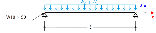
Uvažujme prostý nosníku ASTM A992 W 18x50 s vlastní tíhou a spojitým užitným zatížením, jak je znázorněno na obrázku 1. Maximální jmenovitá výška prutu je 18 palců. Průhyb při užitném zatížení je omezen na L/360. Nosník je prostě podepřen a spojitě ztužen. Ověřte dostupnou pevnost v ohybu vybraného nosníku na základě LRFD a ASD.
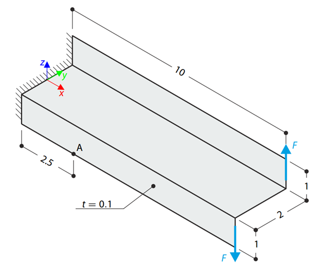
Konzola s Z-profilem je na konci plně fixována a zatížena kroutícím momentem, který je v případě skořepinového modelu reprezentován dvojicí posouvajících sil. Stanoví se normálové napětí v bodě A (ve středu plochy). Problém je definován podle normy NAFEMS Benchmarks.
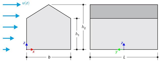
Verifikační příklad porovnává výpočet zatížení větrem na budovu se sedlovou střechou podle normy EN 1991-1-4 a pomocí CFD simulace v programu RWIND Simulation. The building is defined according to the sketch, and the inflow velocity profile is taken according to the standard EN 1991-1-4.
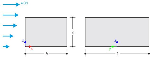
Verifikační příklad porovnává výpočet zatížení větrem na budovu s plochou střechou podle normy EN 1991-1-4 a pomocí CFD simulace v programu RWIND Simulation. The building is defined according to the sketch, and the inflow velocity profile is taken according to the standard EN 1991-1-4.

Prut s W-profilem podle ASTM A992 je vybrán tak, aby unesl vlastní tíhu 30 000 kips a užitné zatížení 90 000 kips v tahu. Verify the member strength using both LRFD and ASD.
Consider an ASTM A992 W 18×50 beam forspan and uniform dead and live loads as shown in Figure 1. Maximální jmenovitá výška prutu je 18 palců. The live load deflection is limited to L/360. The beam is simply supported and continuously braced. Verify the available flexural strength of the selected beam, based on LRFD and ASD.
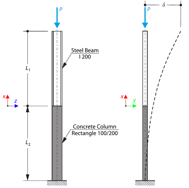
A column is composed of a concrete section (rectangle 100/200) and a steel section (profile I 200). Je vystaven tlakové síle. Determine the critical load and corresponding load factor. The theoretical solution is based on the buckling of a simple beam. In this case, two regions have to be taken into account due to different moments of inertia and material properties.
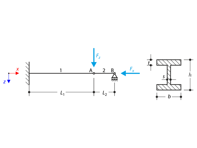
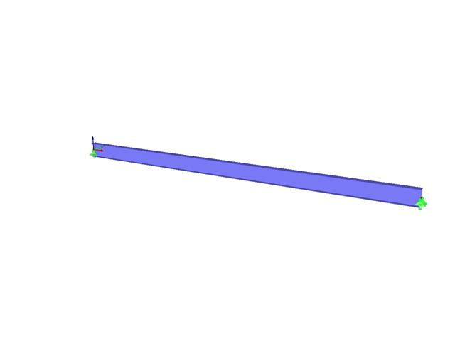
A structure made of an I-profile is fully fixed on the left end and embedded into the sliding support on the right end. Konstrukce se skládá ze dvou segmentů. The self-weight is neglected in this example. Determine the maximum deflection of the structure, the bending moment on the fixed end, the rotation of segment 2, and the reaction force at point B by means of the geometrically linear analysis and the second-order analysis. The verification example is based on the example introduced by Gensichen and Lumpe.
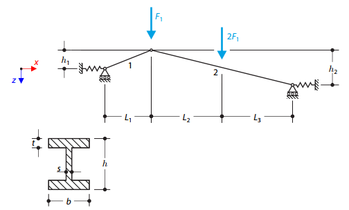
A structure made of I-profile trusses is supported on both ends by spring sliding supports and loaded by transversal forces. Vlastní tíha se v tomto příkladu nezohledňuje. Determine the deflection of the structure, the bending moment, the normal force in the given test points, and the horizontal deflection of the spring supports.
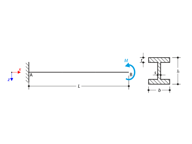
Konzola s I-profilem je podepřena na levém konci a zatížena momentem. The aim of this example is to compare the fixed support with the fork support and to investigate the behavior of some representative quantities. Comparison is also made to the solution by means of plates. Small deformations are considered, and the self-weight is neglected. Determine the rotation in the midpoint of the cantilever, and in case of the member entity with warping, determine the values of the primary torsional moment, the secondary torsional moment, and the warping moment both on the left end (point A) and the right end (point B).