Structural Engineering | NOBA Hallenbau GmbH Hauptstraße 45 92665 Altenstadt, Germany |
DIY Store in Obertraubling, Germany
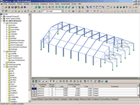
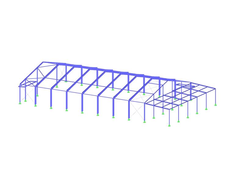
The steel frame structure consists of a double-hinged and built-on frame canopy as well as glass roofing.
Project Specifications
Model data
Number of Nodes
140
Number of Members
235
Number of Load Cases
14
Number of Load Combinations
15
Number of Result Combinations
2
Total Weight
28.431 tons
Dimensions
145.51 x 81.2 x 25.16 feet
Program Version
8.00.38
Do you have any questions?
In this article, you will learn how to model and design cable structures in RFEM 6 or RSTAB 9.
This article describes and explains the influence of bending stiffness of cables on their internal forces. Furthermore, the text provides information on how this influence can be reduced.
The ASCE 7-22 Standard [1], Sect. 12.9.1.6 specifies when P-delta effects should be considered when running a modal response spectrum analysis for seismic design. In the NBC 2020 [2], Sent. 4.1.8.3.8.c gives only a short requirement that sway effects due to the interaction of gravity loads with the deformed structure should be considered. Therefore, there may be situations where second-order effects, also known as P-delta, must be considered when carrying out a seismic analysis.
The data exchange between RFEM 6 and Allplan can be done using various file formats. This article describes the data exchange of a determined surface reinforcement using the ASF interface. This allows you to display the RFEM reinforcement values as level curves or colored reinforcement images in Allplan.
Use the "Independent mesh preferred" option in the FE mesh settings to create an independent FE mesh for the integrated objects. This allows you to generate a significantly more detailed and precise FE mesh for individual objects that are integrated into one another.
In the "Edit Section" dialog box, you can display the buckling shapes of the Finite Strip Method (FSM) as a 3D graphic.
In RFEM 6 and RSTAB 9, you have the option to enter "Visual Objects" as guide objects. You can import the file formats 3ds, stl, and obj.
These objects allow you to create a better reference to the dimensions.
- Design of five types of seismic force-resisting systems (SFRS) includes Special Moment Frame (SMF), Intermediate Moment Frame (IMF), Ordinary Moment Frame (OMF), Ordinary Concentrically Braced Frame (OCBF), and Special Concentrically Braced Frame (SCBF)
- Ductility check of the width-to thickness ratios for webs and flanges
- Calculation of the required strength and stiffness for stability bracing of beams
- Calculation of the maximum spacing for stability bracing of beams
- Calculation of the required strength at hinge locations for stability bracing of beams
- Calculation of the column required strength with the option to neglect all bending moments, shear, and torsion for overstrength limit state
- Design check of column and brace slenderness ratios
Recommended Products for You