Hundertwasser Tower in Kuchlbauer's World of Beer in Abensberg, Germany
Customer Project
The Kuchlbauer tower is an architectural project built on the premises of the German brewery Kuchlbauer in Abensberg, Germany. The tower with a height of 34.19 m was designed by the Austrian artist Friedrich Stowasser, better known as Friedensreich Hundertwasser. Unfortunately, he died in 2000 when the project was still in its planning stages.
Structural Engineering |
Engineering office for structural planning and fire protection Uhrmacher GmbH, Abensberg, Germany www.diestatiker.de |
Architect |
Peter Pelikan Vienna, Austria |
Construction |
Gruener Janura AG Glarus, Switzerland |
Investor |
Brauerei zum Kuchlbauer GmbH & Co. KG, Abensberg www.kuchlbauer.de |
Model
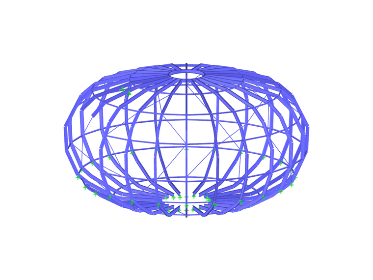
The following information refers to the calculated structure of the roof ball in RSTAB.Approx. Length: 10 m | Width: 10 m | Height: 5.5 m | Mass: 4.2 t
Nonlinear Effects: tension members
Number of Nodes: 348 | Members: 508 | Materials: 1 | Cross-Sections: 6
The tower was designed by F. Hundertwasser, who died in 2000 when the project was still in its planning stages. The exhibition inside the tower shows the brewing procedure and informs about the German purity law. In addition, visitors can see a collection of more than 4,000 wheat bear glasses.
The platform offers a splendid view of Abensberg and the Hallertau region in Germany which is the largest hop-planting area in the world.
Construction Completed After Death of Hundertwasser
The tower was built when Hundertwasser had already died. It was erected under the direction of architect Peter Pelikan and building owner Leonard Sallek who is also the owner of the brewery. Discussions were carried out on the part of the town Abensberg concerning monument protection. Finally the first foundation stone was laid in April 2007 and the golden roof ball was put on the tower top in August 2008. In January 2010, the tower opened its doors for the first time.Roof Ball Structure
The German engineering office Uhrmacher, operators of the Internet planning portal www.diestatiker.de, was responsible for the tower structural analysis. They used the Dlubal's structural analysis and design software.The supporting structure of the roof ball consisting of 508 steel members was calculated with RSTAB. It has a diameter of 10 m. The total mass of the ball including coating is 12 tons. The construction of the tower required approximately 140 t of reinforcing steel and 15 t of I‑beams.
Write Comment...
Write Comment...
Contact us
Do you have questions or need advice?
Contact our free e-mail, chat, or forum support or find various suggested solutions and useful tips on our FAQ page.

New
CSA S16:19 Stability Considerations and the New Annex O.2
Structure stability is not a new phenomenon when referring to steel design. The Canadian steel design standard CSA S16 and the most recent 2019 release is no exception.

SHAPE-THIN determines the effective cross-sections according to EN 1993-1-3 and EN 1993-1-5 for cold-formed sections. You can optionally check the geometric conditions for the applicability of the standard specified in EN 1993‑1‑3, Section 5.2.
The effects of local plate buckling are considered according to the method of reduced widths and the possible buckling of stiffeners (instability) is considered for stiffened sections according to EN 1993-1-3, Section 5.5.
As an option, you can perform an iterative calculation to optimize the effective cross-section.
You can display the effective cross-sections graphically.
Read more about designing cold-formed sections with SHAPE-THIN and RF-/STEEL Cold-Formed Sections in this technical article: Design of a Thin-Walled, Cold-Formed C-Section According to EN 1993-1-3.
- In connection with the calculation according to the large deformation analysis, I get significantly smaller deformations than for the calculation according to the linear static or second-order analysis. How is this possible?
- How is it possible to consider the real cross-section geometry of member elements in RWIND Simulation?
- Is it also possible to simulate an external steel structure in RWIND Simulation?
-
The upper and lower flanges have to be joined by a column, but there are the verticals and diagonals connected to the flanges.
How do I arrange the hinges? - Is it possible in RF‑/TOWER Loading to display the intermediate steps for determining the wind load, such as the fullness coefficient?
-
Why are my steel members not being designed for stability in RF-STEEL AISC?
- My section is classified as Class 4 and non-designable in RF-/STEEL CSA. However, my manual calculation shows a different class. Why the difference?
- I have defined temperature loads, strain loads, or a precamber. As soon as I modify stiffnesses, the deformations are no longer plausible.
- Can the properties, such as B. the cross -section or the surface thickness as well as the material of a surface of an existing element for a new element?
- I am trying to manually check the deformations from the CRANEWAY add-on module. However, I obtain great deviations. How to explain the differences?
Programs Used for Structural Analysis