


The pavilion is located at the Technical University of Kaiserslautern Architecture Faculty’s new timber research campus. The structure serves as the building entrance.
The structural analysis and design for this unique, one-of-a-kind building was carried out by PIRMIN JUNG. For the cross-laminated timber (CLT) surface design, as well as the connections, the engineers of PIRMIN JUNG used the RFEM finite element program. The Digital Timber Construction DTC research group at the Technical University of Kaiserslautern was headed by Jun. Prof Dr. Christopher Robeller. This group developed software to manufacture light timber CLT panel structures.
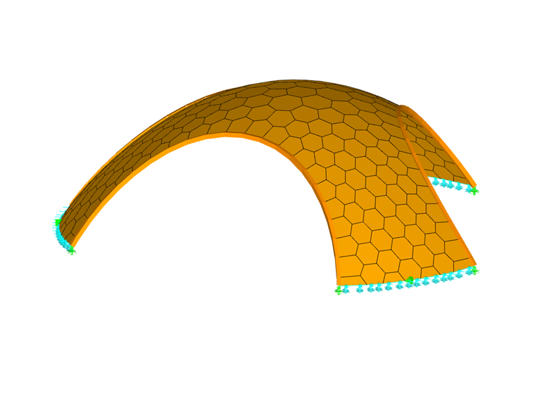
Structure
The wooden pavilion is approximately 13 ft high and spans 39 ft. Three large arched wings stem from the domed roof and connect to the foundation. The shell structure consists of 3.94-inch-thick CLT panels. Because the components are subjected to little bending - rather, mainly to compression - fewer materials were required.
The pentagonal to heptagonal arch components required a mathematical algorithm. More than 200 unique geometrical surfaces about 24 inches wide were created through computer calculations. These small components were manufactured from scrap pieces typically deemed as waste during the production of multi-story building wall elements.
The adjacent panels are connected with glued-in beech dowels and X-fix connectors, which are plywood dovetail-shaped timber-to-timber connectors. The X-fix connectors resist the tension and shear forces resulting from the adjacent in-plane surface displacement. They also ensure gap-free connection for the panels during assembly. The glued-in beech dowels fix the plates and transfer the transverse forces acting perpendicular to the plates.
The entire project was completed in eight short weeks, from the initial planning to the final construction. The production and assembly itself took only eight days. Load tests using six OSB panels with a height of 4.59 ft (corresponding to a weight of about 18.7 tons) were able to verify the dome’s mathematically proven high load-bearing capacity after the completion of the construction.
| Location | Technical University of Kaiserslautern Erwin-Schrödinger-Strasse 52 67663 Kaiserslautern Germany |
| Owner | Technical University of Kaiserslautern, Germany www.uni-kl.de |
| Architectural Design | Jun. Prof. Dr. Christopher Robeller "Digital Timber Construction DTC" Technical University of Kaiserslautern www.uni-kl.de |
| Structural Design | PIRMIN JUNG www.pirminjung.de |
| Timber Structure | CLTECH GmbH & Co. KG cltech.de |


