


The "Extended Display" button allows for a targeted evaluation of the results for each stress point. It opens the "Cross-Section Properties and Stress Distribution" dialog box (Image 01).
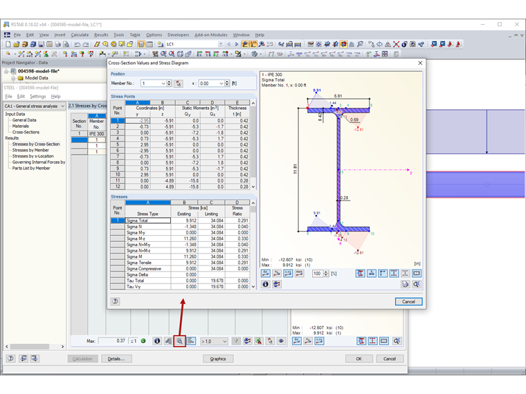
In the "Position" section, the current member number and location x on the member are preset. You can also select other members or x‑locations in the list.
The "Stress Points" section lists all stress points of the cross-section. The "Coordinates" columns show the centroidal distances y and z, and the "Static moments" columns show the surface moments of the first degree Sy and Sz. The "Thickness t" column shows the thickness of the cross-section part that is required for the determination of shear stresses. In the case of closed cross-sections, the cell area A* is specified, which is required for the determination of the stress due to torsional moment.
The "Stresses" section shows all stresses at the current stress point (selected in the section above). In this dialog box, it is also possible to select a stress type with a mouse click to display the stress diagrams in the graphic.