


Shear Joint Resistance
In EN 1992‑1‑1, the designs imply the calculational shear stresses. In this case, the joint strength is composed of the proportions of the adhesive bonding (vRdi,ad), the friction at the interface (vRdi,r), and the shear force reinforcement part (vRdi,sy) from the clamping and anchor effect, whereby the maximum shear resistance is limited by the reduced compressive strength (vRdi,max) of the new or old concrete.
vRdi = vRdi,ad + vRdi,r + vRdi,sy ≤ vRdi,max
![Design Model for Bonded Joint Resistance According to [1]](/en/webimage/009526/2419234/01-en-png.png?mw=760&hash=7ec548270c812e4679005b311ca774da4860d51a)
The existing shear reinforcement can be applied as the bond reinforcement. The design value of the shear resistance is calculated and divided into the individual components as follows:
vRdi = c · fctd + μ · σn + ρ · fyd · (1.2 μ · sin α + cos α) ≤ 0.5 · ν · fcd
where
c, μ, ν are the factors that depend on the roughness of the interface
- indented: c = 0.50 | μ = 0.90 | ν = 0.70
- rough: c = 0.40 a) | μ = 0.70 | ν = 0.50
- smooth: c = 0.20 a) | μ = 0.60 | ν = 0.20
- very smooth: c = 0 b) | μ = 0.50 | ν = 0
a) Tension across the interface: c = 0.
b) Higher factors must be based on the corresponding designs.
fctd is the design value of concrete tensile strength according to 3.1.6 (2)P
σn is the stress per unit area caused by the minimum external normal force across the interface that can act simultaneously with the shear force (positive for compression)
ρ = As / Ai
As is the area of reinforcement crossing the interface, including ordinary shear reinforcement (if any), with adequate anchorage on both sides of the interface
Ai is the area of the joint, transferred by the shear
α is the inclination angle of the reinforcement, limited by 45° ≤ α ≤ 90°
The classification of surfaces as very smooth, smooth, rough, or indented depends on the specific conditions during concreting, concrete properties, and concrete cure, and the relevant literature can be applied.
Design Shear Stress at Interface
The design value of the shear stress in the interface is determined as follows:
where
β is the ratio of the longitudinal force in the new concrete area and the total longitudinal force either in the compression or tension zone in the section considered
VEd is the design value of the applied shear force
z is the lever arm of the composite section
bi is the width of the interface
Alternatively, you can calculate the shear force on the basis of the longitudinal force difference in the new concrete area using the general stress integration. To do this, click the [Details] button in the module and in the "Ultimate Limit State" tab, then select the option titled "Difference of longitudinal force in the added concrete part from general integration of stresses". In contrast to the standard provisions, this option also considers the moment Mz,Ed.
Design of Shear Joints
Shear joint design is based on the relation vEdi ≤ vRdi.
Considering Shear Joints in RF-CONCRETE Members
In RF‑CONCRETE Members, the shear joints can be taken into account in Window 1.6 Reinforcement under the "Shear Joint" tab. After selecting the "Shear joint available" option, all other options for the exact description of the shear joint become accessible. Here, you can define the position of the shear joint precisely. There is the "Transition plate‑web" option, which, on one hand, is probably the most frequently used option in the case of T‑beams. On the other hand, it is also possible to specify the distance from the top or bottom side of the beam.
In the list box, you can select the surface classification in accordance with EN 1992‑1‑1, 6.2.5 (2). The applied parameters are displayed in the list. If necessary, you can adjust the parameters by changing the design standard or the National Annex.
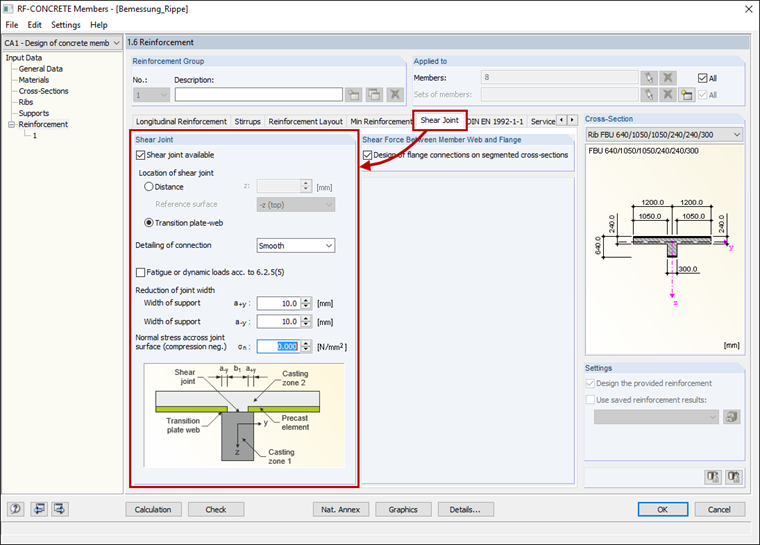
Also, you can select whether to apply EN 1992‑1‑1, 6.2.5 (5) when neglecting the adhesion component of the concrete bonding in the case of dynamic or fatigue loads.
In order to determine the correct joint width, it is necessary to enter the width of support of the connected element slabs. It is important to ensure that this value is not greater than the lateral concrete cover, if possible; otherwise, the shear reinforcement cannot be inserted, thus the design is not fulfilled.
Last but not least, you can define normal stress across the joint surface. Here, the minimum normal force across the interface that can act simultaneously with the shear force should apply. For compression, the force is positive; for tension, the force is negative. If there is tensile force, the adhesion component of the concrete bonding is set to 0 and not applied.
Results of the Shear Joint Design
Windows 2.1 to 2.4 show the resulting required reinforcement. These results can be displayed by cross‑section, set of members, member, or x‑location. The result of the required reinforcement for the shear joint is displayed together with the result of the shear reinforcement asw,V,stirrup. In the "Detailed Results" table, you can see some intermediate values of the shear joint design. These intermediate values are listed under "Shear at the interface between concrete cast at different times".
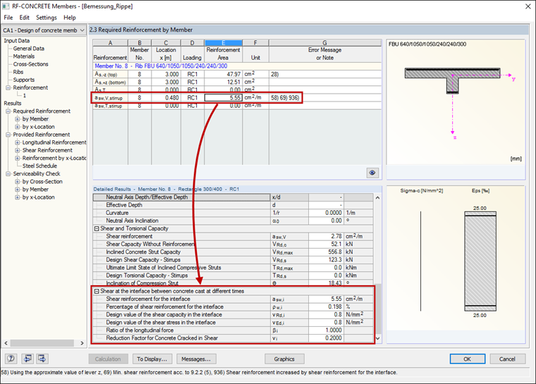
If Note 936) appears next to the value of asw,V,stirrup, this means that the bond reinforcement of the shear joint governs for the shear reinforcement design.