Stress formula 12.3.3-1 for occasional loads according to EN 13480-3:
The stress σ2 is comprised of three parts. Internal pressure is the first part. The other two parts only differ by the index of the moment. The moment MA is composed of sustained mechanical loads (for example, the piping or fluid weight). The moment MB represents the occasional loads (for example, wind or snow). Therefore, it is necessary to calculate the moment portions separately. Only one moment would return to a piping load combination. Thus, the design according to the formula cannot be performed. This can be solved by using result combinations. In result combinations, you can add or subtract the results of load cases or combinations. The individual parts are thus known and can be designed separately from one another.
The following figure shows an example of a combination structure for the occasional design situation. The final combination and the combination provided for the design are highlighted in red.
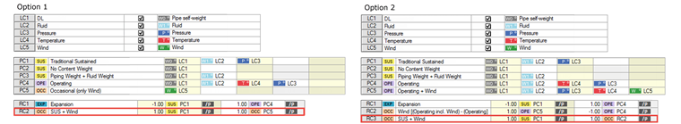
Option 1
In the combination shown in Option 1, a piping load combination is entered with the attribute "OCC" for the wind load case. This PC5 is then combined with traditional sustained loads in a new result combination RC2. The moment can thus be divided into the individual portions MA and MB.
Option 2
In Option 2, the action of the wind loads in combination with the other load cases is examined more precisely. A new piping load combination (PC5) is entered, which has a similar structure to PC4 and includes a wind load case. In RC2, these two operating stress situations are subtracted from each other, so that only the internal forces of the wind and possibly the effects from the second-order analysis remain. These internal forces are subsequently superimposed with traditional sustained loads in a further RC.
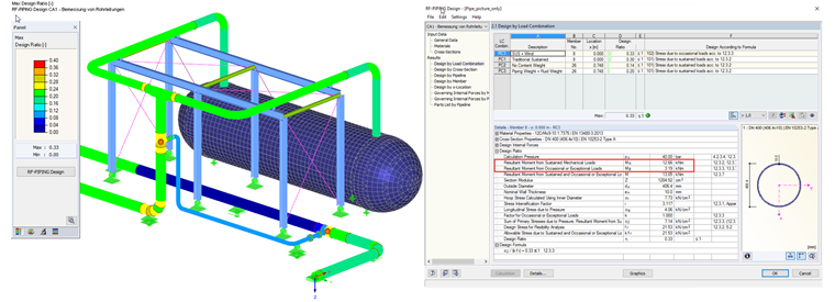
The following picture of the RF-PIPING Design module shows the design. The resulting moment portions MA and MB are also displayed.