


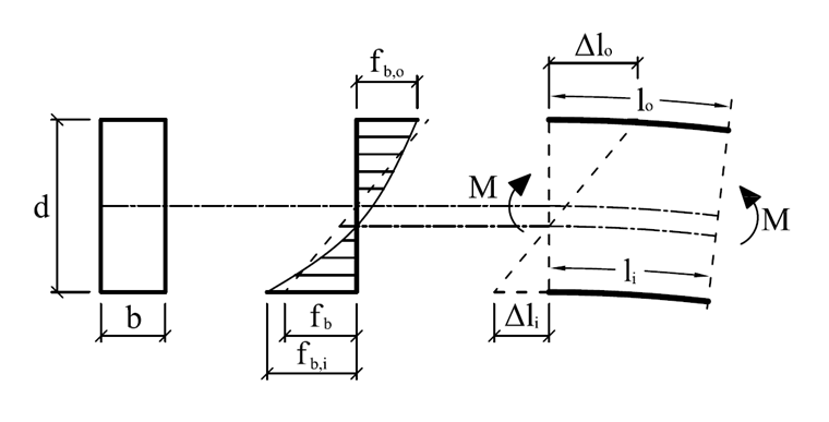
Due to the geometric shape and manufacturing process of curved glued-laminated timber, it is necessary to perform separate checks during the design. For one thing, the distribution of the bending stress along the beam depth is not linear; furthermore, stresses occur during manufacture due to the bending of the lamellas. The former is due to the fact that the grains on the inside are shorter than those on the outside. Thus, the following applies, assuming Bernoulli's assumptions (flat cross-sections remain flat), and assuming that the zero line is in the center of gravity:
Taking into account Hooke's law, the inner edge stresses are larger than the outer ones:
fb = E ∙ ε → fb,i > fb,o
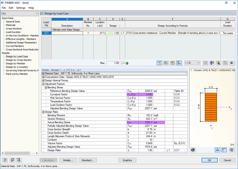
These characteristics are taken into account in the design according to [1] with the Curvature Factor Cc, which serves as an adjustment factor for the design value of the flexural strength:
Fb' = Fb ∙ CD ∙ CM ∙ Ct ∙ CV ∙ Cc
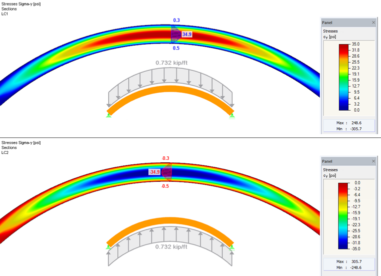
For the system shown in Figure 03, taking into account 20 times its own weight and a linear stress distribution, a maximum bending stress in the ridge cross-section of 1,925.1 psi results. Considering the stresses in an FEM analysis (see Figure 03 below), as explained above, larger bending stresses (1,986.4 psi) are displayed as expected.
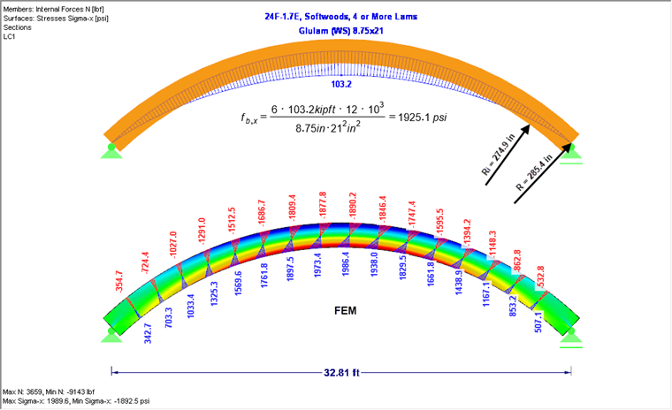
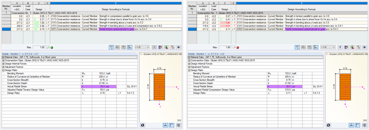
For the design of the curved beams in RF-/TIMBER AWC, this discrepancy with the Curvature Factor Cc is taken into account, as required in [1] (see Figure 04).
If the bending moment increases the radius of curvature, additional tensile stresses transverse to the grain occur. If the bending moment reduces the radius of curvature, compressive stresses occur across the grain. A schematic representation of how these stresses occur is shown in Figure 05, taking into account a linear longitudinal stress distribution (fb,x).
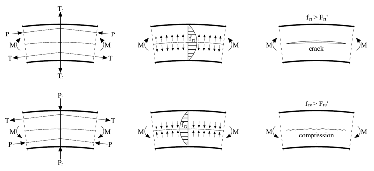
These radial stresses must be taken into account in the design, since they have a decisive influence on the load capacity. They result in a constant cross-section over the beam depth to:
The stresses become maximal at the height of the neutral axis, from which follows:
Since these radial stresses cannot be detected with a beam (1D), these must be determined analytically. Figure 06 shows the results from the FEM calculation (2D) for transverse (top) and lateral (bottom). The results are almost identical to the analytical solution used for beam design in RF-/TIMBER AWC (see Figure 07).
If the check is not provided, the timber will crack at the level of the neutral axis (see Figure 05 on the right). To prevent this, transversal tensile reinforcements can be screwed in, for example in the form of fully threaded screws, which absorb the transversal tension stresses. The force acting on the screw can be approximately determined manually as follows:
Tr,t = frt ∙ b ∙ s = 35.4 psi ∙ 8.75 in. ∙ 11.5 in. = 3.562 lbf
Tr,t = radial force in screw
frt = radial tension stress
b = beam width
s = spacing between radial reinforcement
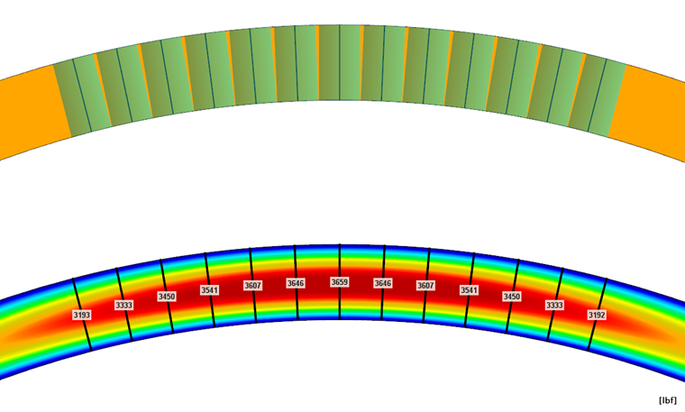
In the case of a surface model in RFEM, these forces can be integrated directly from the internal forces in surfaces onto a result beam. This result beam does not bring any further rigidity into the system, but only integrates the internal forces in surfaces. Thus, the normal force of the beam or the reinforcing element can be read directly (see Figure 08).
With RFEM, even more complex forms of support can be designed in detail. If the shapes of the beams deviate from the standardized shapes of beams, an FEM calculation with surfaces can be helpful, as described above.