Ultimate Limit State Design for Timber Structures
As mentioned above, the largest ratio of the components usually results from the highest loading. In most European and American standards, however, the strength of the timber depends on the load duration and timber humidity. Therefore, it can happen that a load combination governs even if it does not have the largest loading in relation to the amount. For this reason, it is important to pay attention to find the governing load combinations. This is shown graphically in Figure 01.
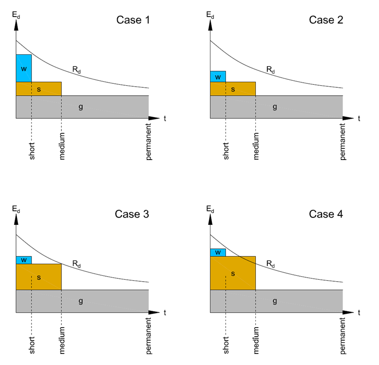
Ed = design value of loading
Rd = design value of strength
t = load duration
g = permanent load
s = snow load
w = wind load
Case 1:
Governing load combination = g + s + w
Reason: Loading from g + s + w is nearest to the curve Rd.
Case 2:
Governing load combination = g
Reason: Loading from g is nearest to the curve Rd.
Case 3:
Governing load combination = g + s
Reason: Loading from g + s is nearest to the curve Rd.
Case 4:
Governing load combination = g + s
Reason: Loading from g + s exceeds curve Rd → Ed > Rd.
The influence of the load duration is considered in [1] with the modification coefficient kmod. In [2], this situation is managed with the CD factor (ASD) and λ factor (LRFD). The Swiss standard [3] simply defines the influence of the load duration on the strength with the factor ηM and is thus identical for all actions; Figure 01 is, therefore, not valid in this case.
Serviceability Limit State Design for Timber Structures
When performing serviceability limit state design, the largest deflections occur when all deflection ratios of the unfavorable actions are considered. According to [1], the following deformations have to be analyzed; for example, for the German and Austrian Annex:
- elastic initial deformation winst
consisting of the characteristic combination - final deformation wfin
consisting of the characteristic initial deformation and the creep ratios of the quasi-permanent combination - final deformation wfin,net
consisting of the quasi-permanent initial deformation and the creep ratios of the quasi-permanent combination. It is also calculated with the characteristic initial deformation for other countries, but this is considered too "strict" according to the German and Austrian Annexes.
Number [2] does not explicitly explain which load cases have to be used to determine load combinations for the serviceability. It is referred to the generally accepted construction engineering standards. In this case, the IBC (International Building Code) [4] can be used to determine the governing load combination (see Chapter 1604.3). Only considering creep is explained in [2]. In contrast to other European standards, the IBC considers actions with regard to deformations separately. Limit values result only from imposed loads, snow, or wind for the deformation and in case of creep from self-weight + imposed load.
According to [3], the following limit states have to be analyzed; among other things:
- rare design situation
consisting of the characteristic initial deformation and the creep ratios of the quasi-permanent combination - frequent design situation
consisting of the frequent initial deformation and the creep ratios of the quasi-permanent combination - quasi-permanent design situation
consisting of the quasi-permanent initial deformation and the creep ratios of the quasi-permanent combination
Considering Load Duration, Timber Humidity, and Creep in RFEM and RSTAB
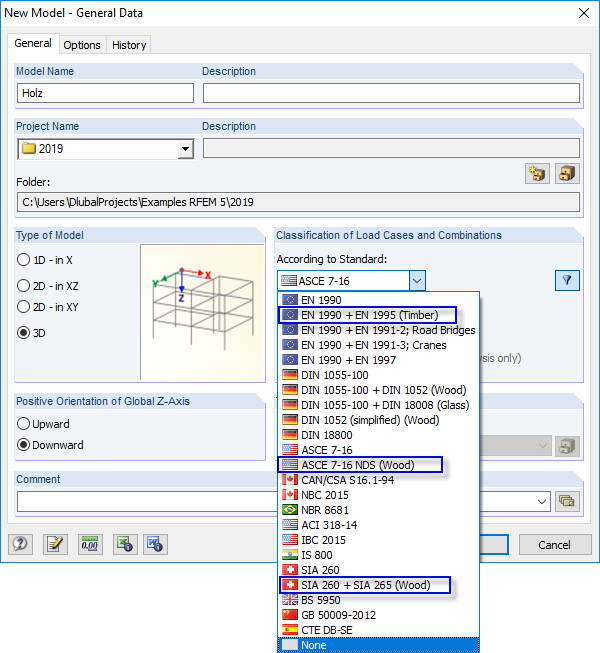
To take into account load duration, timber humidity, and creep, RFEM and RSTAB contain separate standards to classify load cases and combinations thereof. "Timber" is added at the relevant standard.
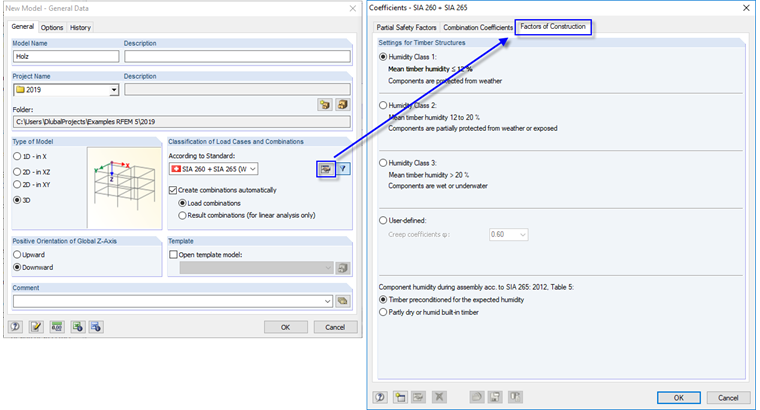
In the properties of the relevant standard, it is possible to set standard-specific settings such as the definition of the creeping coefficient. The necessary settings are thus made to create the load combination.
To consider the influence of the load duration during the design, the relevant load duration is defined when creating the load case.
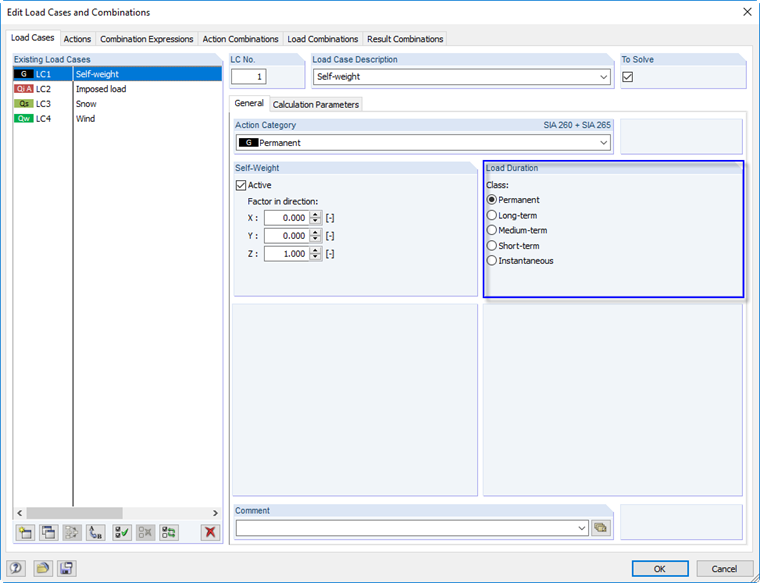
It is automatically taken over in the design modules (RF-/TIMBER Pro, RF-/TIMBER AWC, RF-LAMINATE, and so on) and assigned to the individual load combinations.
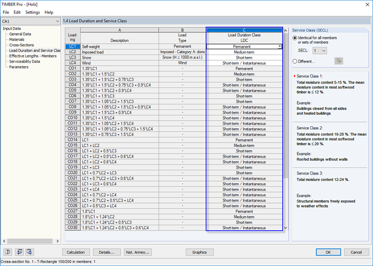
It is then ensured that the ultimate limit state design of each load combination is always carried out with the shortest load duration of the contained load cases.
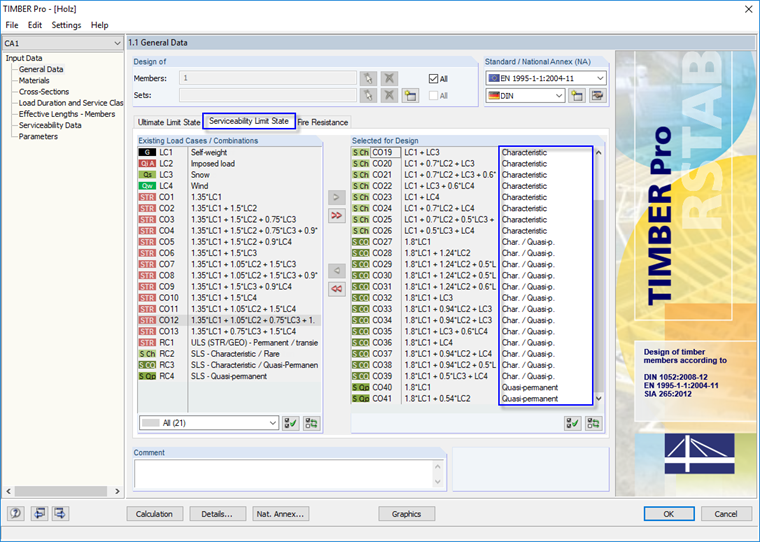
For the serviceability limit state, the limit values of the relevant design situation are assigned in the general data of the corresponding add-on module. If the load combinations are generated manually, without using the automatic load combination, the assignment has to be done manually as well.
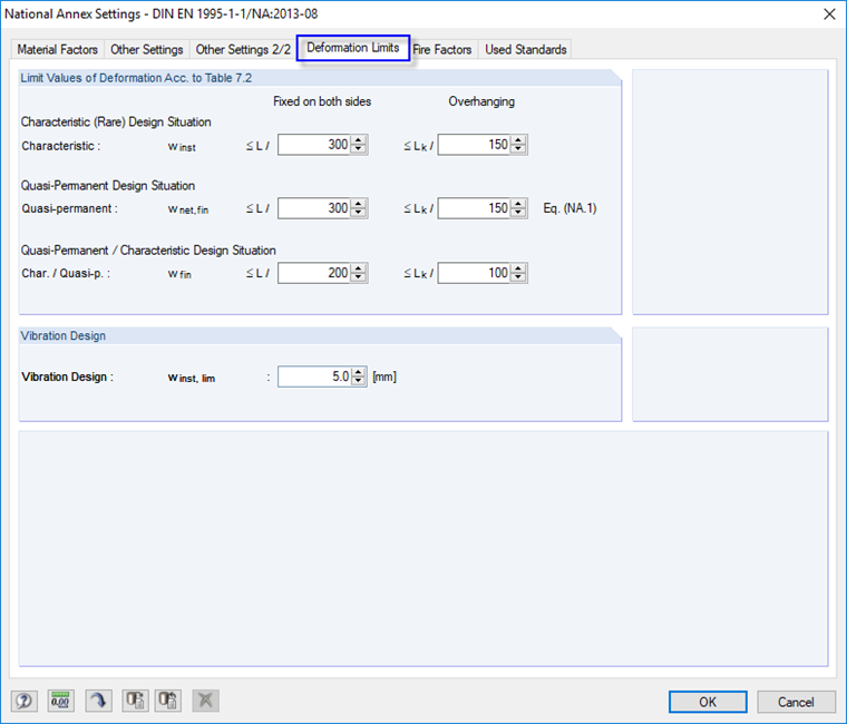
The limit values can be adjusted in the settings of the standard or in the settings of the National Annex for the relevant design situation.