


Two Walls Without Considering Intermediate Ceiling
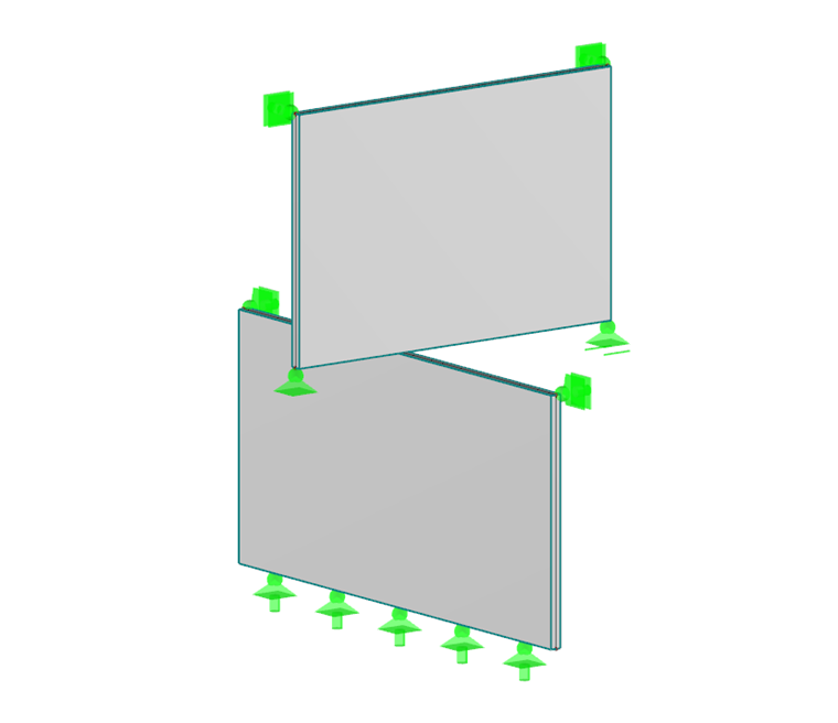
In the first example, the bottom wall is supported by lines on its bottom side and supported laterally by the top two corners, while the top wall is point-supported at all four nodes. The only contact between the two walls is the contact node, where the top wall rests on the bottom wall (see Image 01). Activate the "Connect Members/Lines" function so that this contact node will be generated automatically during the modeling.
The nodal release can then be defined as described in the linked Knowledge Base article, where, of course, the required degrees of freedom or nonlinearities, for example "Fixed if Vz positive", can be set within the release.
After selecting the corresponding node, the surface to release, and a line of which the axis system is used to align the nodal release, you can start the calculation. You can see the results of the nodal release in Table "4.50 Nodal Releases – Forces". In this case, the contact force is Vz, (see Image 02, Release No. 1) Find more information about defining nodal releases on pages 177-178 in the RFEM manual [1].

Two Walls with Consideration of Intermediate Ceiling
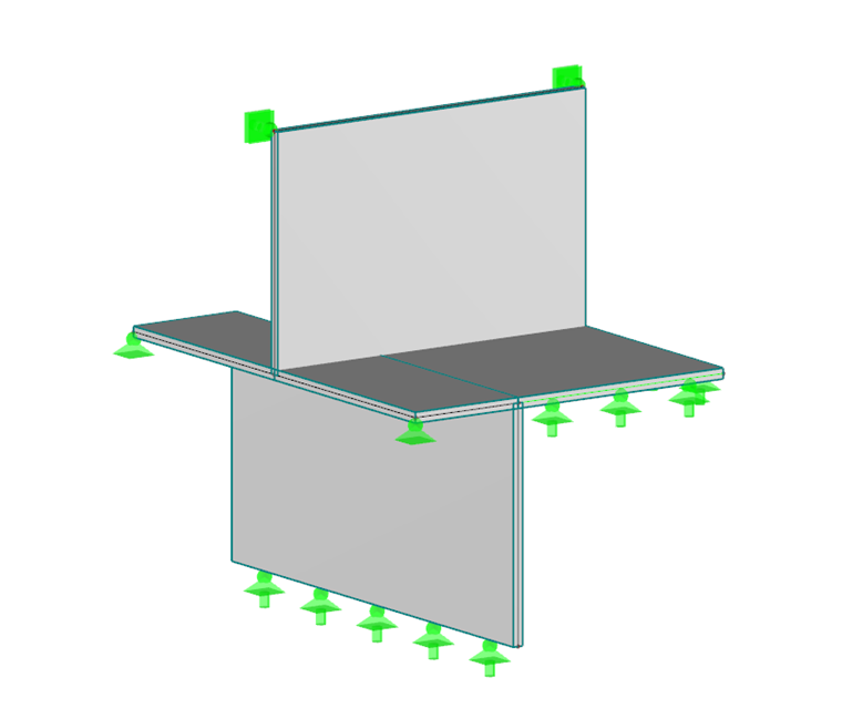
In the second example, a concrete floor is added to the intermediate level (see Image 03), which is, of course, important for the load transfer and thus influences the contact forces between the two walls.
You have to define a nodal release again here at the same location as in the first example, but due to the intermediate ceiling, you have to pay attention to a particularity regarding the nodal release.
The nodal release always generates new nodes and changes the end node of all lines belonging to the released surface (here, Surface 4, top wall). If Surface 4 is to be released, the bottom Boundary Lines 16 and 35 of this surface will end in a new generated node. At the same time, however, they should end in the original node as well, since lines 16 and 35 are also boundary lines of Surfaces 5, 6, and 7 (suspended ceiling). Since these requirements cannot be fulfilled at the same time, the additional definition of a line release at lines 16 and 35 is required here, so that two additional required lines will be generated internally. Find more information about defining a line release on pages 181-182 in the RFEM manual [1].
Due to the additional load transfer of the intermediate ceiling, the contact force Vz of the nodal release is only 22 kN compared to 55.12 kN from the first example (see Image 02, Release 2).
