


The model of this technical article is based on the system of a gusset plate attached to a column, which is described in more detail on Page 8.67 in [1].
Structural System
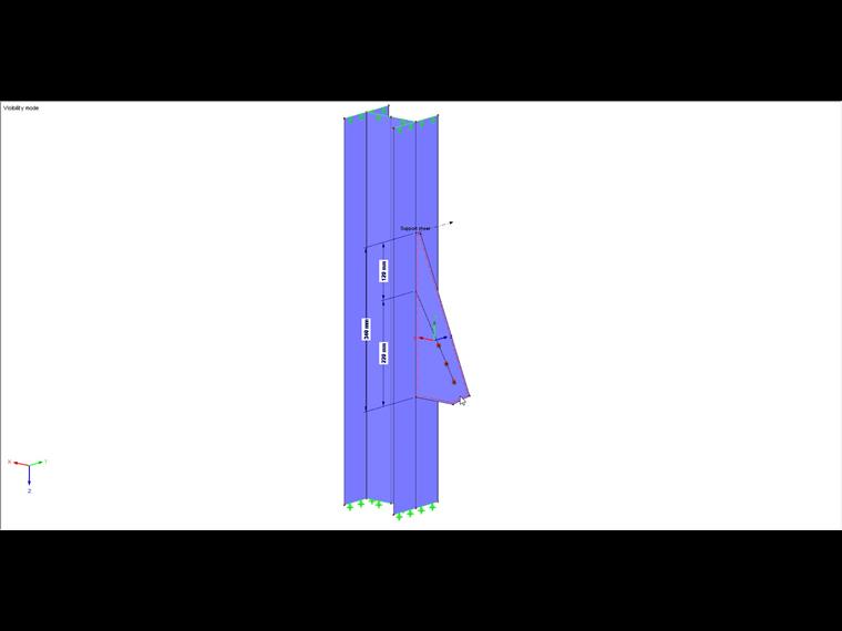
Basically, the system consists of an HEB 140 column, to the flange of which a gusset plate is to be welded by means of a double fillet weld. This plate connects the column with a tension member, which should be ignored. The acting load is 330 kN and is allocated to the three bolt holes in the system. Although the load is known here, the required forces should be determined from the internal forces of the gusset plate. The load serves only for verification purposes.
Determination of Resultant
The formula for the resultant is taken from Table 8.66c in [1].
The individual force components can be calculated as follows.
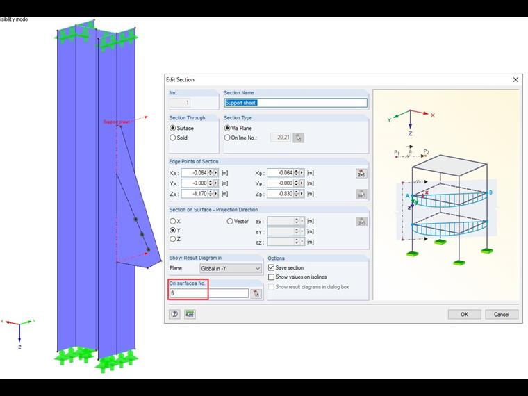
The forces F as well as the moment can be determined by defining a section. In the section dialog box, only the gusset plate should be considered.
Method 1
After the calculation, you can graphically display the section resultants for each section.
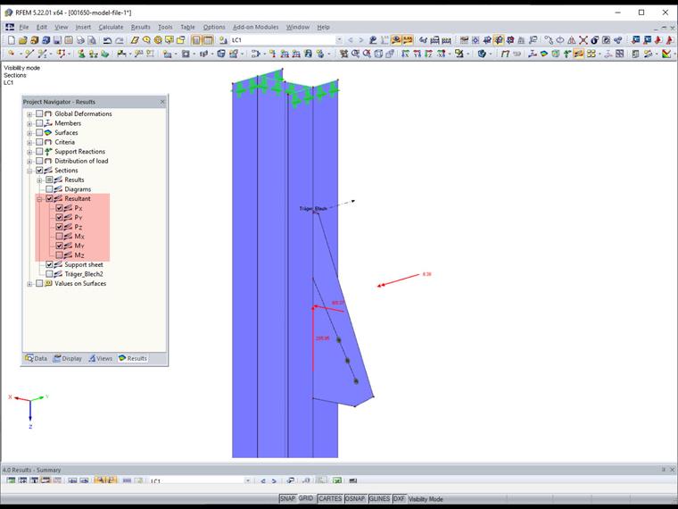
These values can now be inserted in the corresponding formulas. The assignment of the resultants to forces is as follows in this example.
F1⊥,Ed = PX = 165.37 kN
F2⊥,Ed = PY = 0 kN
Fll,Ed = PZ = 285.95 kN
MEd = MY = 8.38 kNm
Since the section resultants are arranged analogously to the global axes, further result transformations would be necessary for welds or sections lying elsewhere, in order to get the corresponding forces and moments. Therefore, we show another method.
Method 2
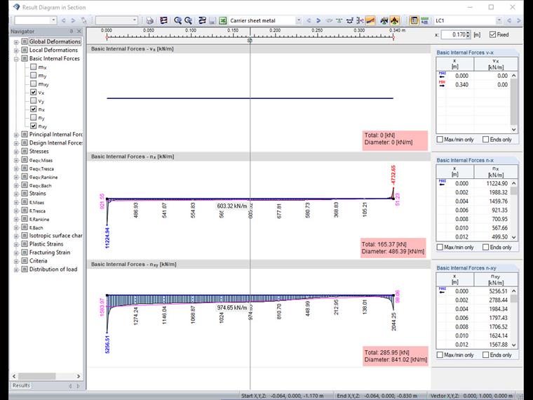
Again, the section already created can be used. The corresponding result diagram is opened for further evaluation.
Taking into account the local surface-axis system, the basic internal forces vx (= 0 as there are no horizontal loads) and nx as well as nxy are represented. The result interpretation of the diagrams again provides the required forces. Another calculation is required only for the determination of the moment. For this, the intermediate values of the basic internal force nx are exported to the Excel spreadsheet. Then, the moment results from the sum of the forces of the individual segments multiplied by the corresponding distance to the center of the section.
The results of both methods are identical. A mental check by decomposing the force of 330 kN acting at an angle of 30° also results in the force pairs and the moment of:
F⊥,Ed = 330 ⋅ sin 30 ° = 165 kN
Fll,Ed = 330 ⋅ cos 30 ° = 285 kN
MEd = 165 ⋅ 0.05 = 8.3 kNm
Design of Fillet Weld
The resultant can now be determined by means of the forces and the moment.
N⊥,Ed = 165 / 34 + 8.38 / ( 34² / 6 ) = 9.20 kN/cm
V⊥,Ed = 0
Vll,Ed = 286 / 34 = 8.41 kN/cm
Fw,Ed = √ 9.2² + 8.41² = 12.46 kN/cm
Finally, this is compared to the design value of the ultimate limit state of the fillet weld. The fillet weld thickness is assumed to be 3 mm.
Fw,Rd = ( 36 / √ 3 ⋅ 0.8 ⋅ 1.25 ) ⋅ 2 ⋅ 0.3 = 12.47 kN/cm
Fw,Ed = 12.46 kN/cm < Fw,Rd = 12.47 kN/cm
