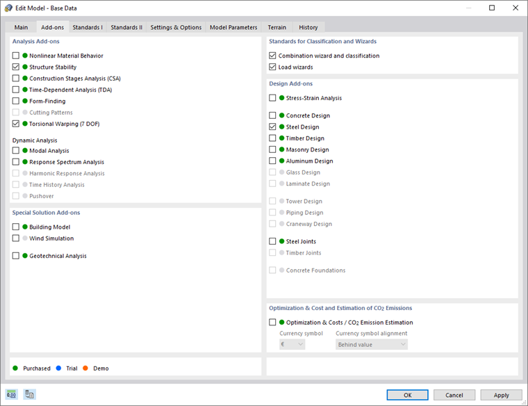
Activating Add-ons
The Torsional Warping (7 DOF) add-on is activated in the Base Data of a model. In order to also calculate the critical load factor for lateral-torsional buckling and apply the mode shape as the initial shape of the imperfection, it is necessary to also activate the Structure Stability add-on. For steel beam design according to EN 1993‑1‑1, the Steel Design add-on is activated.
Boundary Conditions for Calculation with Torsional Warping
The add-on extends the calculation of member elements by the 7th degree of freedom. This is not a separate calculation by "separating" the individual members, but a calculation on the entire model. The stiffness of the adjacent members or defined support conditions is thus taken into account directly. Since the warping is considered as a local member internal force, no further global support conditions have to be defined for the warping.
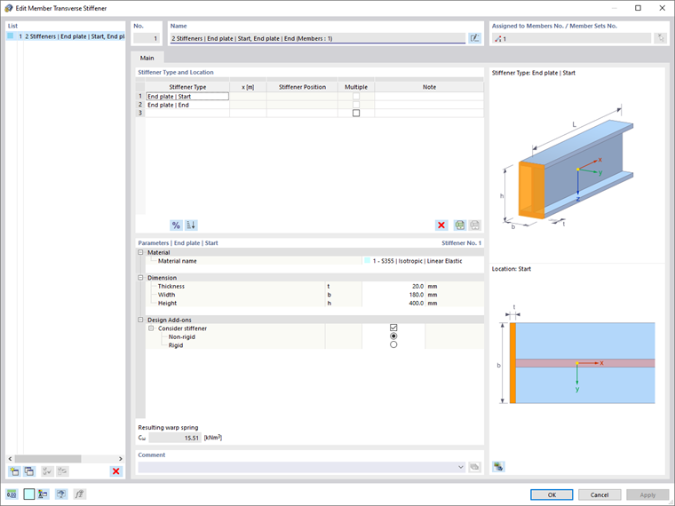
In order to consider the warping stiffness or the warping stress for a member, you can use the member transverse stiffeners. For example, you can define end plate dimensions and the conversion to a warp spring is performed automatically.
By default, the warping is assumed to be unhindered at each member end, and is not transferred between the adjacent members. To consider the warping between two members as continuous, you can create a set of members.
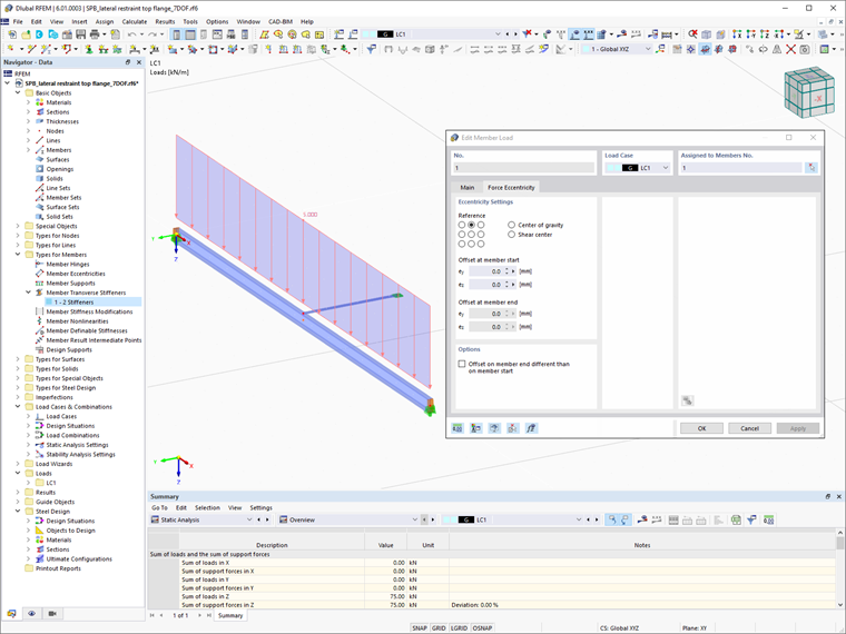
Load Application Point
When calculating with 7 degrees of freedom, the defined member loads are assumed in the centroid of the cross-section. To modify the load application point, you can assign an eccentricity to the loads in the Edit Dialog box. Likewise, the connections to the adjacent members or nodal supports are assumed in the centroid. Use member eccentricities or rigid members as a modeling tool to define eccentric connections.
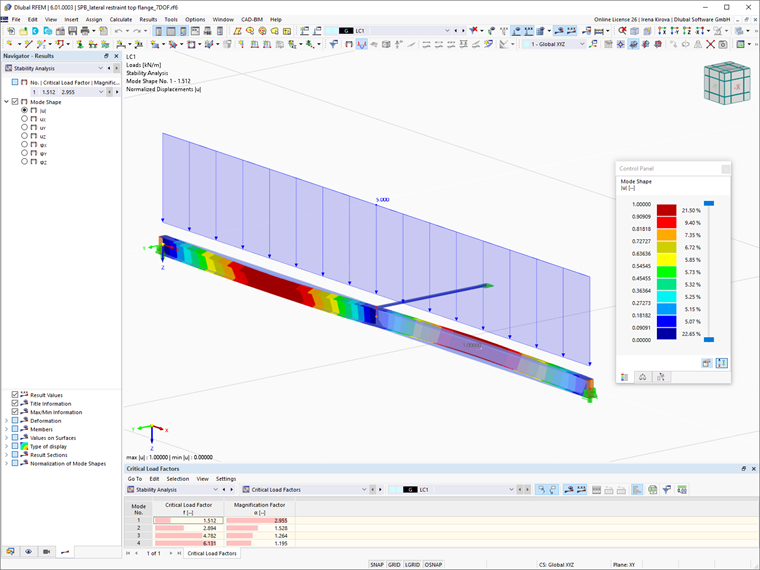
Stability Analysis Software
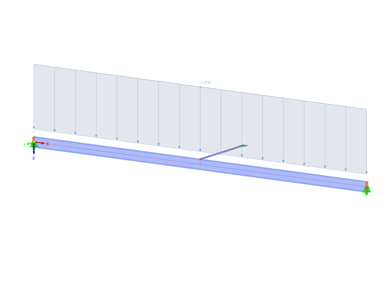
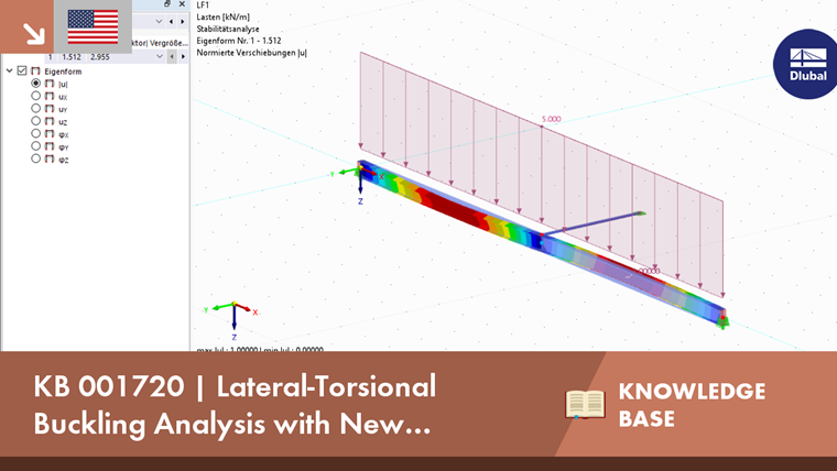
By activating the "Perform stability analysis" option in a load case, you can analyze the stability of the structure subjected to the loading of the load case. The eigenvalue analysis taking into account the 7th degree of freedom is also able to recognize the failure modes of torsional buckling and lateral-torsional buckling in addition to flexural buckling, as well as to calculate the critical load factor. The mode shape and critical load factors can be displayed in the results of the stability analysis.
Applying Imperfections from Scaled Mode Shape
The imperfections required for the lateral-torsional buckling analysis can be generated by scaling the mode shape. To do this, create an imperfection case of the "Buckling Mode" type and select the corresponding mode shape as the initial shape. By specifying the imperfection direction and the magnitude according to the standard, the precamber is generated using the FE mesh pre-deformation.
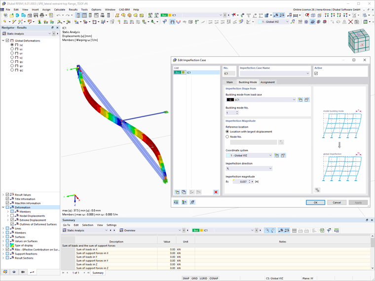
Now, you can consider the imperfection in a load combination when determining internal forces. Since the large deformation values occur especially in the case of the loads close to the critical load in combination with imperfections, we recommend performing a calculation according to the large deformation analysis in order to determine the internal forces exactly.
Steel Design
Steel design takes into account the internal forces from the calculation with Torsional Warping when performing the design according to EN 1993‑1‑1. If these components are greater than the limit values set in the ultimate limit state configuration at one location, an equivalent stress analysis is performed (taking into account the effective cross-section properties, if necessary). Since this example includes a stability analysis, it is necessary to use the partial safety factor γM1 for the design. Make this setting in the ultimate limit state configuration. You can deactivate the other stability design checks.
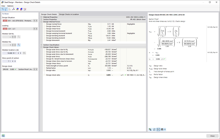
As an alternative, you can use the Stress-Strain Analysis add-on for a simple equivalent stress analysis. It is currently impossible to perform plastic design with internal forces from the calculation with Torsional Warping.