


Therefore, their yield rules can only apply to pure elastic-plastic material behavior. For materials subjected to a damage process by cracks, for example, the material model described below is more suitable. A good example of such a material is concrete, which has substantially higher compressive strength against tensile strength. The cracks occurring in the tension area of the material reduce the stiffness of the system. In the case of reinforced concrete or reinforced fiber concrete, the reinforcement absorbs the tensile stresses.
Theoretical Background
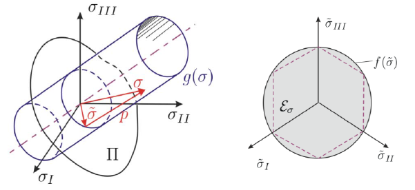
Generally, nonlinear material models are represented by shifting the system in the current deformed space towards a stress-free reference configuration (see Image 02). You can find more information about this topic in [2], for example.
![Kinematic Relationship Between Reference and Current Configuration (Source: [1])](/en/webimage/009485/2419059/02-en-3-png.png)
The deformations of the local element are represented in the reference system using a strain tensor. The strains in the undeformed reference system can be derived using the Green-Lagrange strain tensor E = ½ ∙ (FT ∙ F - 1), and the strains in the local coordinate system using the Euler-Almansi strain tensor e = ½ ∙ (I - b-1). Of these two strains, the linear strain ε = ½ ∙ (H + HT) is obtained using the partial integration, and it is used to calculate nominal stresses on the system using Cauchy's theorem and the Piola-Kirchhoff stress tensor. Thus, free energy rates can be determined over the balance equations of the continuum.
Balance equations of the continuum:
- Mass balance means that the system mass remains the same, even if it is deformed.
- Momentum balance as a temporal change of the total momentum
- Angular momentum balance as a change speed of the total momentum
- First law of thermodynamics: The total energy of a system is constant.
kinetic energy = mechanical power + stress surface - Second law of thermodynamics: In the case of a transfer into another plane, the energy (heat) is released.
Equations of state (constitutive equations) describe the material relationship between the solids. The internal variables (free energy ψ, specific entropy s, Cauchy's stress tensor σ, heat flux vector q) are used to consider the damage in the material model. In this context, the material "memory", the time-dependent behavior, also plays an important role. This is taken into account by the kinematic and isotropic strain hardening. With regard to the damage to the material, the strain component is decomposed into an elastic and a plastic portion. The plastic portion is decomposed again into a kinematic and an isotropic portion.
ε = εe + εp → εp = εiso + εkin
The article about the nonlinear elastic material behavior already explained that the yield function, which considers the damage effects, depends on the invariants of the stress tensor. Specifically, the yield function is governed by a so-called Kuhn-Tucker condition, which states that all stress states within the principal stress space are less than 0 and thus elastic. Stresses outside this area are not allowed and are projected back onto the yield surface during the corrector step (predictor-corrector step). This calculation is performed as a test function, which necessitates the nonlinear calculation method according to Newton-Raphson.
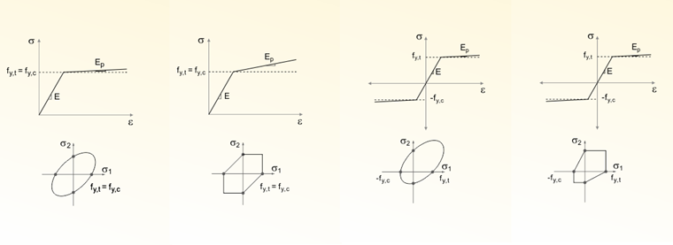
The yield function (from [4]) in the Damage material model differentiates the material between the tensile and the compressive stress:
In this case, r is the energy rate and h is the strain hardening of the function. Variables A and B indicate the material damage. This is also performed similarly to the next chapter by using a stress-strain diagram in the principal stress space.
Damage in RFEM
After a basic introduction to the subject, this article further explains how to handle the material model in RFEM. Within this article, is is only possible to provide a rough overview so there may also be gaps in the context. For this reason, further literature such as [2] is recommended.
Due to the nonlinear calculation method with the correction step, it is necessary to perform the linear elastic calculation in the first step of the diagram. The solution in RFEM provides the strain in the second step of the diagram dependent on the elastic modulus, which is defined in the material dialog box, and on the defined limit stress (see Image 04).
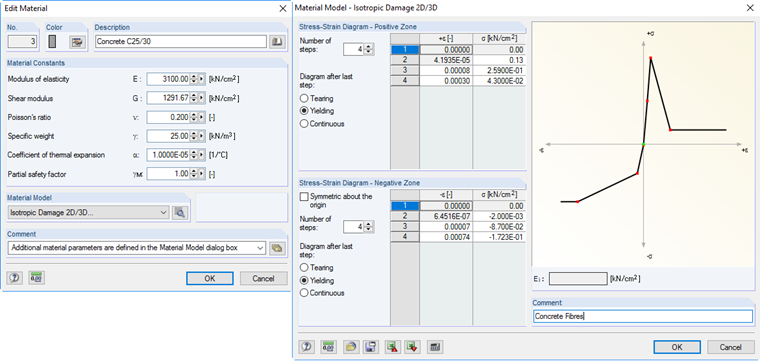
In this case, the strain is governed by Hooke's law ε = σ / E. After this first elastic predictor step, you can carry out an almost arbitrary antimetric definition of the stress-strain diagram. It is also possible for the elastic modulus of the material to be negative, given that it is recalculated as follows:
However, since the elastic module is only necessary to recalculate the relation, the amount of the modulus is also allowed. In the case of the Damage material model, the described calculation using correction iteration ensures that the stiffness of the system is reduced until the individual FE element no longer absorbs any stress. The strains in the respective element can be very large.
Summary
The Damage material model allows for nonlinear calculation with antimetric, almost arbitrary stress-strain diagrams. If the material is damaged, the system remains as a continuum, though. That is, no cracks occur in the system. The numerical effort for this would be very substantial. For example, it is necessary to generate a new system meshing with an adaptive FE mesh. Due to these limits, very large strains may arise in the system.
In the case of very high strains, you can divide the system manually. For this, contact solids with the corresponding similar yield strength can be used. Furthermore, a plastic distortion of the element is not considered when using this material model, which can be particularly helpful in the compression area. For the common problem of the concrete cracked in the tension area, the material model is sufficiently accurate.