These result from a planned eccentric load introduction, imperfect structures (geometric and material imperfections), and an additional eccentricity from the calculation according to the second-order analysis.
Planned Eccentricities
The eccentricities from the planned eccentric load introduction can be easily determined with the moments due to an eccentric load application. For a constant moment distribution, the following relation applies:
In this case, the minimum eccentricity according to 6.1.(4) is
where h is the cross-section depth.For a linearly variable moment distribution, an equivalent eccentricity may be determined and the following formula applied:
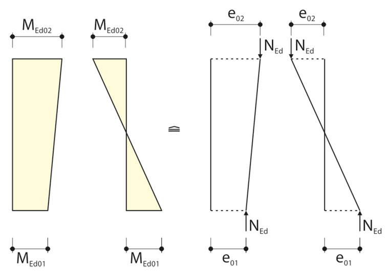
The eccentricities have to be applied with algebraic signs. They have the same sign if the related moments create tension on the same side.
If there is any moment distribution, the maximum eccentricity is always used for the calculation so that no columns have to be excluded from the analysis.
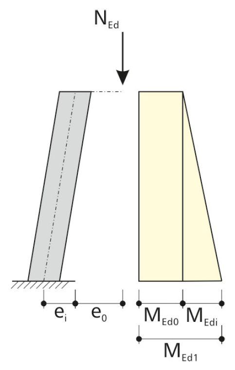
Unintentional Eccentricities Due to Imperfections
For the calculation of the moments according to the linear static analysis, the geometric and material imperfections have to be taken into account as well. This may occur by applying equivalent geometric imperfections, which are considered as the inclination θi.
The eccentricity is determined in EN 1992‑1‑1 according to Formula (5.2):
The inclination θi is calculated according to Formula (5.1):
where:
Basic value of the sway imperfection
Reduction factor for the height
Reduction factor for the number of structural components (m is the number of columns)
This results in the bending moment for the equivalent imperfection ei:
Additional Eccentricity from Calculation According to Second-Order Analysis
Under the axial force load, curvature of the column occurs, with the column head being deflected by the path e2. This results in the moment distribution according to the second-order theory.
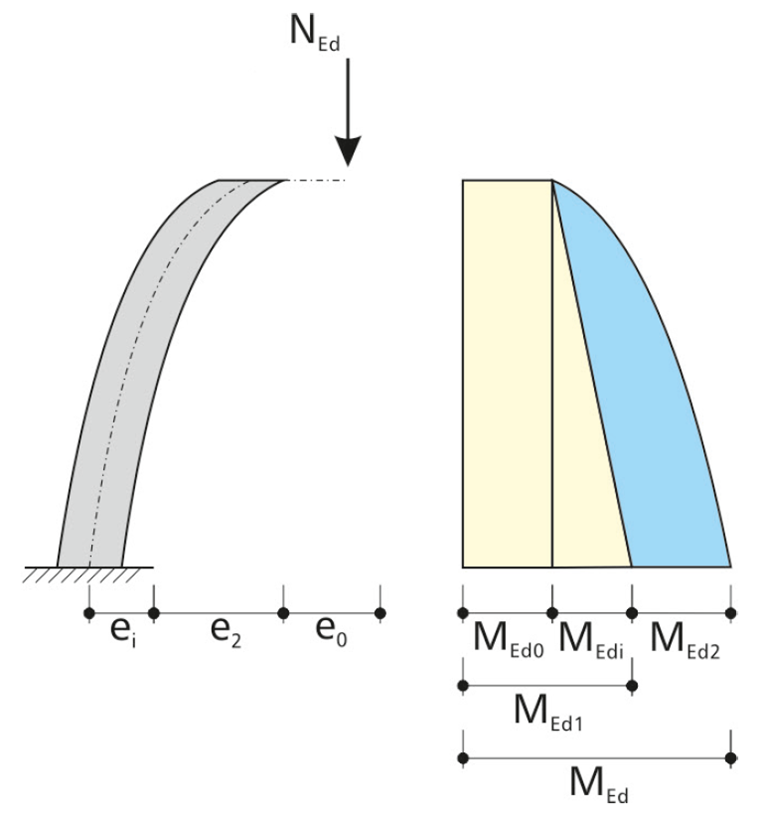
For the method based on nominal curvature, a parabolic moment distribution is assumed. The determination of the eccentricity according to the second-order theory is done according to EN 1992‑1‑1, 5.8.8.2(3).
It can be found in detail in the standard or the manual for (RF-)CONCRETE Columns.
Specifics when Determining the Eccentricities for Biaxial Load Eccentricity
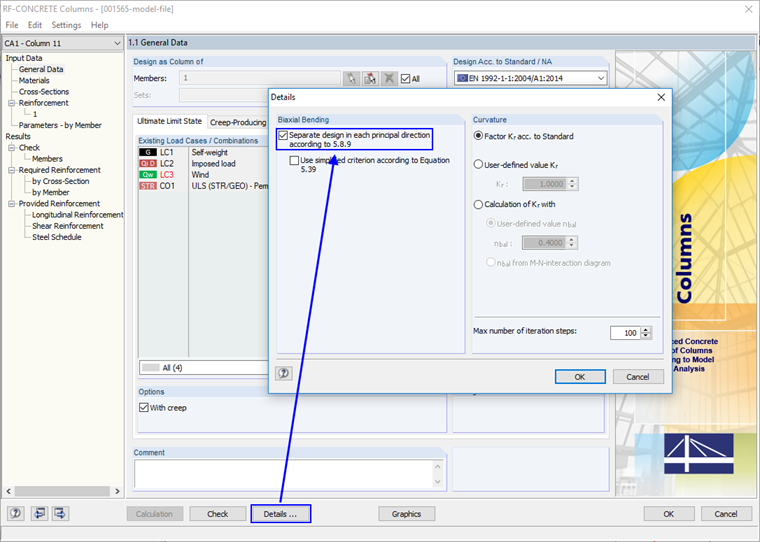
For columns loaded with biaxial load eccentricity, a separate design in both principal axis orientations must be performed first. For this design, the imperfections have to be applied exclusively in the direction where they lead to the most unfavorable effects. The designs can then be performed in both directions with the entire applied reinforcement. Thus, it is a matter of ruling out that the imperfections necessitate a biaxial analysis.
In order to be allowed to perform the designs in both directions without having to consider further biaxial bending, the conditions as per Equation (5.38) have to be fulfilled.
To be able to perform this separate design at all, the corresponding option in (RF-)CONCRETE Columns must be activated first.
On one hand, the slenderness ratio in Equation (5.38a) has to be taken into account:
On the other hand, one of the conditions regarding the related load eccentricities according to Equation (5.38a) has to be fulfilled:
where
iy and iz are the radii of gyration in relation to the y- and z-axes.
are the load eccentricities in the direction of the axes.
When calculating the design moments MEdy and MEdz, the imperfection is not taken into account for the subordinate direction.
The subordinate direction is determined via the ratio of the total eccentricity to the eccentricity according to the linear static analysis.
for the calculation of (5.38b).
Otherwise, ei,z is set to 0.
If this fulfills one of the conditions from equation (5.38b), the design can be performed separately while neglecting the imperfections in the subordinate direction. If (5.38b) is not fulfilled, a biaxial design in consideration of all imperfections must be performed.
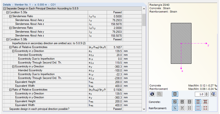
Example Bracket
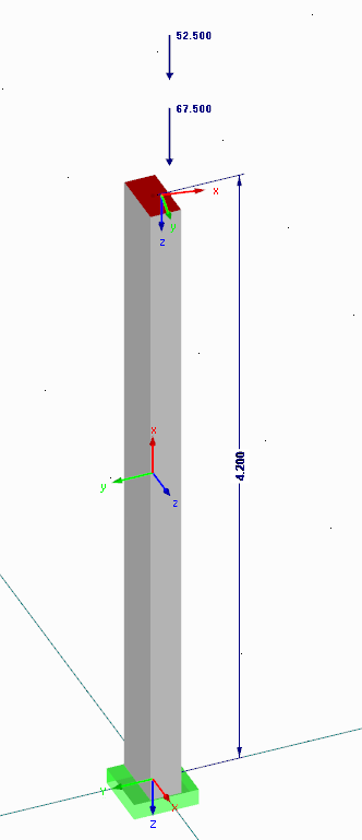
The eccentricities due to the second-order theory are imported from the program:
e2,y = 238 mm
e2,z = 119.5 mm
With these values, it can now be determined which direction is subordinate.
Thus, ei,z can be set to 0, and the values in accordance with Image 06 result.