.png?mw=960&hash=da72dd8fee604f9f2316eac0a719388d5698c608)
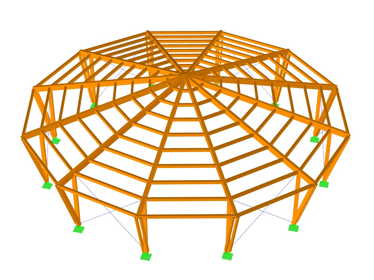
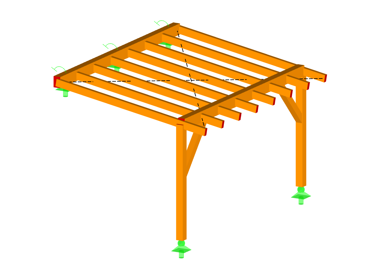
RFEM model of a timber beam ceiling.
Model Used in
- RFEM | Timber Design - Basic
- RFEM | Timber Basics
- Eurocode 5 | Timber Structures According to DIN EN 1995-1-1
- Eurocode 5 | Timber Structures According to DIN EN 1995-1-1
- Eurocode 5 | Timber Structures According to DIN EN 1995-1-1
- Eurocode 5 | Timber Structures According to DIN EN 1995-1-1
- Eurocode 5 | Timber Structures According to EN 1995-1-1
- Eurocode 5 | Timber Structures According to DIN EN 1995-1-1
- Eurocode 5 | Timber Structures According to DIN EN 1995-1-1
- Eurocode 5 | Timber Structures According to DIN EN 1995-1-1
- Eurocode 5 | Timber Structures According to DIN EN 1995-1-1
- Design, Build, Destroy
- Structural Analysis and Design of Timber Structures | Dlubal Software
- Invitation to Online Training "Timber Structures Eurocode 5"
Timber Beam Ceiling
| Number of Nodes | 40 |
| Number of Lines | 38 |
| Number of Members | 38 |
| Number of Surfaces | 0 |
| Number of Solids | 0 |
| Number of Load Cases | 7 |
| Number of Load Combinations | 128 |
| Number of Result Combinations | 2 |
| Total Weight | 2.314 tons |
| Dimensions (Metric) | 12,000 x 0,000 x 10,000 m |
| Dimensions (Imperial) | 39.37 x 0 x 32.81 feet |
You can download this structural model to use it for training purposes or for your projects. However, we do not assume any guarantee or liability for the accuracy or completeness of the model.
Related Models