The model presented in the video demonstrates the use of the equivalent member method according to EN 1993-1-1 (6.3.1 to 6.3.3) for the stability analysis of members and member sets with a uniform cross-section. As soon as a tapered cross-section is present, RF-/STEEL EC3 automatically switches to the general method to ensure applicability in such cases as well. This leads to precise and reliable calculations for varying cross-section shapes.
Model Used in
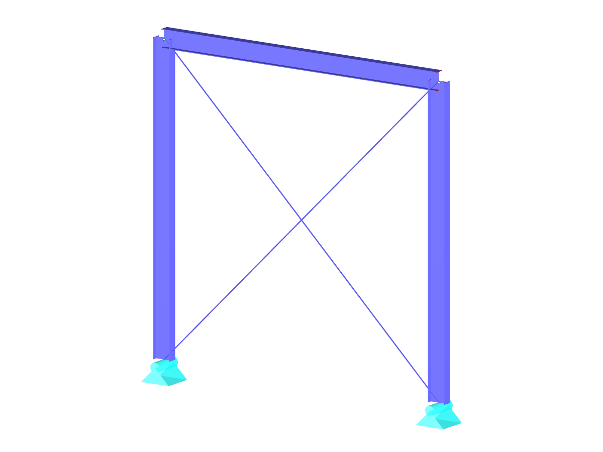
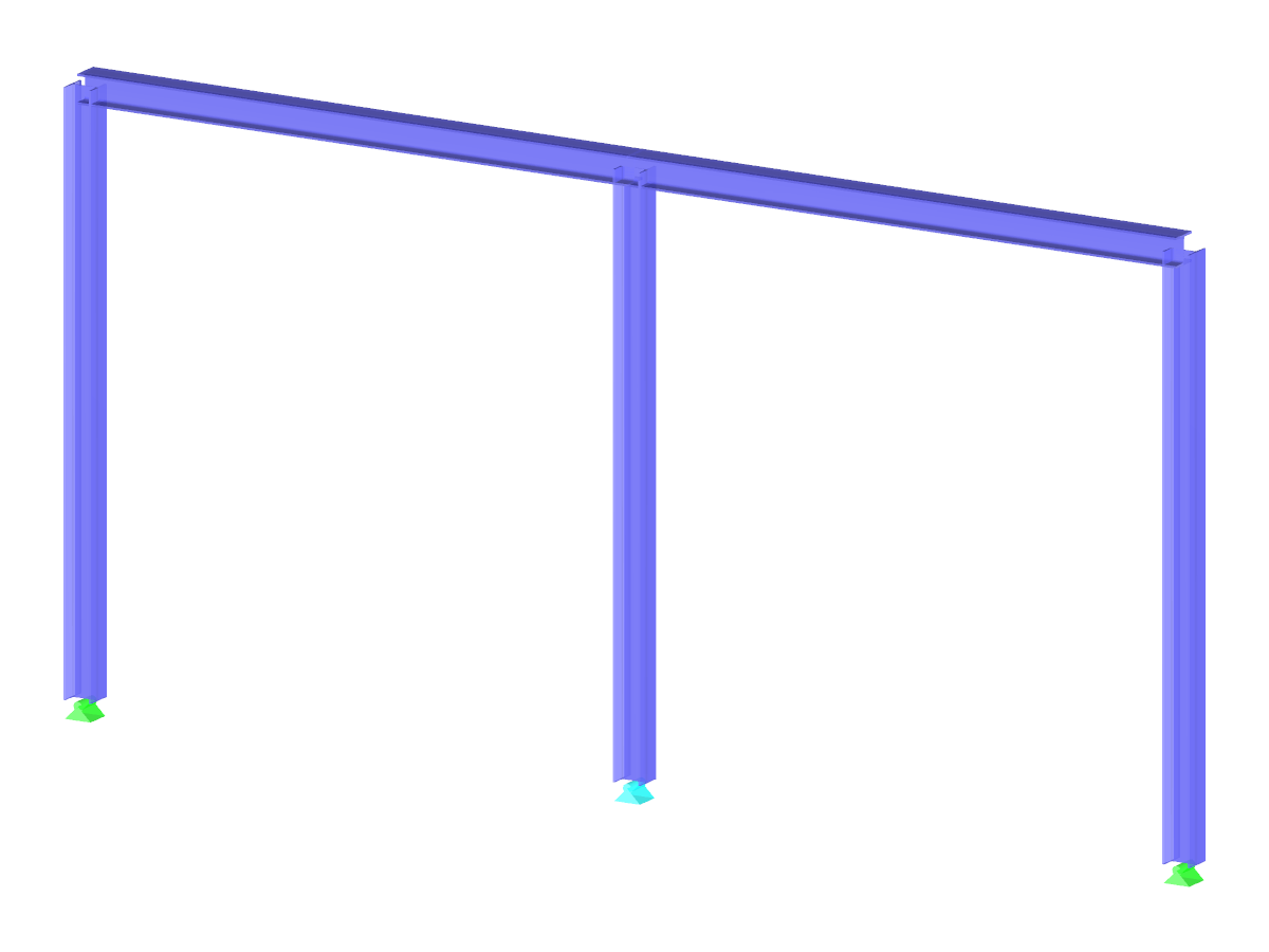
Steel Frame with Tension Members
| Number of Nodes | 8 |
| Number of Members | 16 |
| Number of Load Cases | 2 |
| Total Weight | 1,473 t |
| Dimensions (Metric) | 8.534 x 5.534 x 5.267 m |
| Dimensions (Imperial) | 28 x 18.16 x 17.28 feet |
| Program Version | 8.24.02 |
You can download this structural model to use it for training purposes or for your projects. However, we do not assume any guarantee or liability for the accuracy or completeness of the model.
Related Models