


Description
| Materials | Concrete | Specified concrete compressive strength | f'c | 4000 | psi |
| Flexural reinforcement | Yield strength | fy | 60000 | psi | |
| Headed studs | Yield strength | fyr | 51000 | psi | |
| Geometry | Slab | Slab thickness | h | 7 | in. |
| Concrete cover | c | 0.75 | in. | ||
| Flexural reinforcement nominal diameter | db | 5/8 | in. | ||
| Effective slab depth | d | 5.62 | in. | ||
| Column | Column dimension in x-direction | cx | 12 | in. | |
| Column dimension in y-direction | cy | 20 | in. |
\(
\)
Analytical Solution
1. Calculation of the Effective Slab Depth
The effective slab depth is calculated from the slab thickness, concrete cover, and nominal diameter of the flexural reinforcement:
\(
\mathsf{
d
=
h-c-d_b
}
\)
\(
\mathsf{
=
7.00\,in.
-
0.75\,in.
-
\frac{5}{8}\,in.
=
5.62\,in.
}
\)
2. Calculation of the Critical Section Geometry
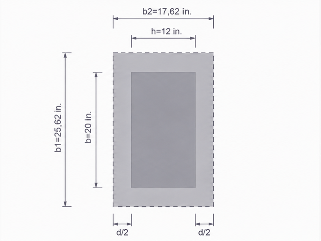
The critical section is located at a distance of \(\mathsf{d/2}\) from the column face.
The dimensions of the critical section are:
\(
\mathsf{
b_1
=
c_x+d
=
12.00\,in.
+
5.62\,in.
=
17.62\,in.
}
\)
\(
\mathsf{
b_2
=
c_y+d
=
20.00\,in.
+
5.62\,in.
=
25.62\,in.
}
\)
The length of the critical perimeter is:
\(
\mathsf{
b_o
=
2\left(b_1+b_2\right)
=
2\left(17.62+25.62\right)
=
86.5\,in.
}
\)
According to the reference solution, the effective area and the polar moment of inertia of the critical section are:
\(
\mathsf{
A_c
=
486\,\mathrm{in.}^{2}
}
\)
\(
\mathsf{
J_c
=
28.0
\times
10^{3}\,\mathrm{in.}^{4}
}
\)
The maximum distance from the centroid of the critical section is:
\(
\mathsf{
x
=
\frac{b_1}{2}
=
\frac{17.62}{2}
=
8.81\,in.
}
\)
3. Calculation of the Fraction of Moment Transferred by Shear
The fraction of the unbalanced moment transferred by eccentric shear is calculated according to ACI 421.1R Eq. (4.2b):
\(
\mathsf{
\gamma_v
=
1
-
\frac{1}
{
1+
\frac{2}{3}
\sqrt{\frac{b_1}{b_2}}
}
}
\)
\(
\mathsf{
=
1
-
\frac{1}
{
1+
\frac{2}{3}
\sqrt{\frac{17.62}{25.62}}
}
=
0.36
}
\)
4. Calculation of the Applied Punching Shear Stress
The maximum punching shear stress is calculated from the direct shear force and the unbalanced moment transferred by eccentric shear:
\(
\mathsf{
v_u
=
\frac{V_u}{A_c}
+
\frac{\gamma_v M_{uy}x}{J_c}
}
\)
\(
\mathsf{
=
\frac{110\times10^{3}\,lb}
{486\,\mathrm{in.}^{2}}
+
\frac{
0.36
\cdot
600\times10^{3}\,lb\,in.
\cdot
8.81\,in.
}
{
28.0\times10^{3}\,\mathrm{in.}^{4}
}
=
294\,psi
}
\)
Using the strength-reduction factor
\(
\mathsf{
\phi
=
0.75
}
\)
the design shear stress is:
\(
\mathsf{
\frac{v_u}{\phi}
=
\frac{294\,psi}{0.75}
=
392\,psi
}
\)
5. Calculation of the Concrete Shear Resistance
The ratio of the long side to the short side of the column is:
\(
\mathsf{
\beta_c
=
\frac{c_y}{c_x}
=
\frac{20}{12}
=
1.67
}
\)
The nominal concrete shear resistance without shear reinforcement is determined from the minimum of the following expressions:
- \(\mathsf{\left(2+\frac{4}{\beta_c}\right)\sqrt{f'_c}}\)
- \(\mathsf{\left(2+\frac{40d}{b_o}\right)\sqrt{f'_c}}\)
- \(\mathsf{4\sqrt{f'_c}}\)
For the present geometry:
\(
\mathsf{
v_n
=
\min
\left[
4.4\sqrt{f'_c},
4.6\sqrt{f'_c},
4.0\sqrt{f'_c}
\right]
=
253\,psi
}
\)
Thus:
\(
\mathsf{
v_n
=
4\sqrt{f'_c}
=
253\,psi
}
\)
Since
\(
\mathsf{
\frac{v_u}{\phi}
=
392\,psi
>
253\,psi
=
v_n
}
\)
headed shear reinforcement is required.
6. Calculation of the Required Shear Reinforcement
In the presence of headed shear reinforcement, the shear stress resisted by the concrete is:
\(
\mathsf{
v_c
=
3\sqrt{f'_c}
=
190\,psi
}
\)
The shear stress to be resisted by the headed studs is therefore:
\(
\mathsf{
v_s
\geq
\frac{v_u}{\phi}
-
v_c
=
392\,psi
-
190\,psi
=
202\,psi
}
\)
The required stud area per spacing is:
\(
\mathsf{
\frac{A_v}{s}
\geq
\frac{v_s b_o}{f_{yt}}
}
\)
\(
\mathsf{
\geq
\frac{
202\,psi
\cdot
86.5\,in.
}
{
51{,}000\,psi
}
=
0.34\,in.
}
\)
7. Selection of the Headed Stud Arrangement
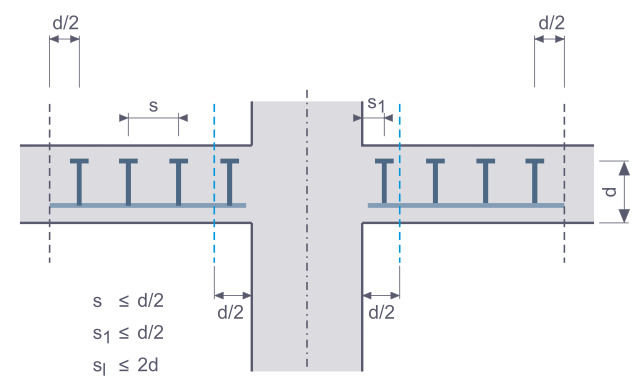
The first peripheral line of studs and the spacing between adjacent peripheral lines must satisfy:
\(
\mathsf{
s_1
\leq
0.5d
}
\)
and
\(
\mathsf{
s
\leq
0.5d
}
\)
With
\(
\mathsf{
0.5d
=
0.5
\cdot
5.62\,in.
=
2.81\,in.
}
\)
the selected values
\(
\mathsf{
s_1
=
2.25\,in.
}
\)
and
\(
\mathsf{
s
=
2.75\,in.
}
\)
satisfy the spacing requirements.
Using ten studs with a cross-sectional area of approximately
\(\mathsf{0.11\,in.^2}\) per stud, the provided stud area per peripheral line is:
\(
\mathsf{
A_v
=
10
\cdot
0.11\,\mathrm{in.}^{2}
=
1.10\,\mathrm{in.}^{2}
}
\)
The provided stud area per spacing is:
\(
\mathsf{
\frac{A_v}{s}
=
\frac{1.10\,\mathrm{in.}^{2}}
{2.75\,in.}
=
0.40\,in.
}
\)
Since
\(
\mathsf{
0.40\,in.
>
0.34\,in.
}
\)
the selected headed shear reinforcement is adequate.
8. Verification of the Outer Critical Section
The outer critical section is located at a distance of \(\mathsf{d/2}\) beyond the outermost peripheral line of studs.
For ten peripheral lines, the distance between the column face and the outermost stud line is:
\(
\mathsf{
s_1
+
9s
=
2.25\,in.
+
9
\cdot
2.75\,in.
=
27.0\,in.
}
\)
Therefore, the distance of the outer critical section from the column face is:
\(
\mathsf{
\alpha d
=
27.0\,in.
+
\frac{5.62\,in.}{2}
=
29.8\,in.
}
\)
The corresponding factor is:
\(
\mathsf{
\alpha
=
\frac{\alpha d}{d}
=
\frac{29.8}{5.62}
=
5.3
}
\)
At this critical section, the design shear stress is:
\(
\mathsf{
\frac{v_u}{\phi}
=
125\,psi
}
\)
The nominal shear resistance outside the shear-reinforced zone is:
\(
\mathsf{
v_n
=
2\sqrt{f'_c}
=
126\,psi
}
\)
Since
\(
\mathsf{
125\,psi
<
126\,psi
}
\)
the extent of the shear-reinforced zone is adequate.
\(
\)
Results
The results from RFEM 6 are presented below.
The RFEM 6 results are compared with the analytical reference solution in the following table.
| Punching shear design according to ACI 318 and ACI 421.1R | |||||
| Parameters | Symbol | Unit | RFEM | Analytical solution | Ratio |
| Effective slab depth | d | in. | 5.625 | 5.620 | 1.001 |
| Critical perimeter at d/2 | bo | in. | 86.50 | 86.50 | 1.000 |
| Polar moment of inertia | Jc | in.4 | 27520.8 | 28000.0 | 0.983 |
| Fraction of moment transferred by shear | γv | [-] | 0.356 | 0.360 | 0.989 |
| Maximum applied shear stress | vu | psi | 313.2 | 294.0 | 1.065 |
| Design shear stress | vu/φ | psi | 417.6 | 392.0 | 1.065 |
| Concrete shear resistance without shear reinforcement | vn | psi | 253.0 | 253.0 | 1.000 |
| Provided stud area per spacing | Av/s | in. | 0.434 | 0.400 | 1.084 |
| Design ratio | η | [-] | 0.951 | 0.992 | 0.958 |
\(
\)
Evaluation
The comparison shows the following:
- The effective slab depth and the critical perimeter are in very good agreement.
- The polar moment of inertia differs by approximately 1.7%. This minor deviation places the RFEM result on the conservative side.
- The largest deviation occurs in the applied punching shear stress and results from the different treatment of moment transfer.
- The concrete shear resistance is reproduced almost exactly.
- The selected headed shear reinforcement satisfies the design requirements.
The selected headed shear reinforcement and the extent of the shear-reinforced zone satisfy the corresponding design requirements.