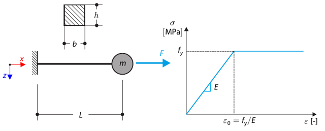
This verification example is based on Verification Example 0122. A single-mass system without damping is subjected to an axial loading force. An ideal elastic-plastic material with characteristics is assumed. Determine the time course of the end-point deflection, velocity, and acceleration.
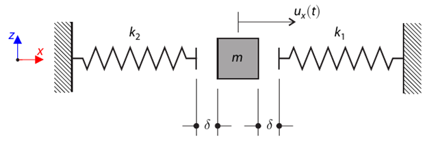
A single-mass system with clearance and two springs is initially deflected. Determine the natural oscillations of the system - deflection, velocity, and acceleration time course.
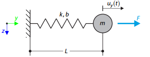
A single mass system is subjected to loading force. Determine the deflection of the system.
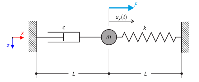
A single-mass system with dashpot is subjected to a constant loading force. Determine the spring force, damping force, and inertial force at the given test time. In this verification example, the Kelvin--Voigt dashpot (namely, a spring and a damper element in serial connection) is decomposed into its purely viscous and purely elastic parts, in order to better evaluate the reaction forces.
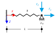
The goal of this example is to demonstrate an irreversible process caused by friction. After the loading and unloading, the end-point is in a different position than where it was at the beginning. Determine the movement of the node in the X direction.
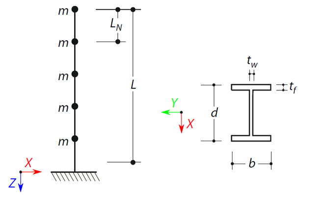
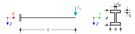
A cantilever beam with an I-beam cross-section of length L is defined. The beam has five mass points with masses m acting in the X-direction. The self-weight is neglected. The frequencies, mode shapes, and equivalent loads of this 5-DOF system are analytically calculated and compared with the results from RSTAB and RFEM.
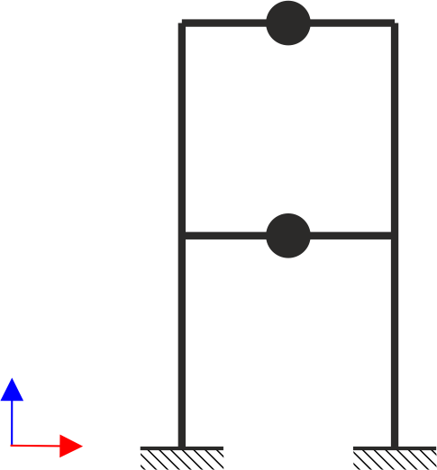
A two‑story, single‑bay frame structure is subjected to earthquake loading. The modulus of elasticity and cross‑section of the frame beams are much larger than those of the columns, so the beams can be considered rigid. The elastic response spectrum is given by the standard SIA 261/1:2003. Neglecting self-weight and assuming the lumped masses are at the floor levels, determine the natural frequencies of the structure. For each frequency obtained, specify the standardized displacements of the floors as well as equivalent forces generated using the elastic response spectrum according to the standard SIA 261/1.2003.

This example compares the effective lengths and critical load factor, which can be calculated in RFEM 6 using the Structure Stability add-on, with a manual calculation. The structural system is a rigid frame with two additional hinged columns. This column is loaded by vertical concentrated loads.
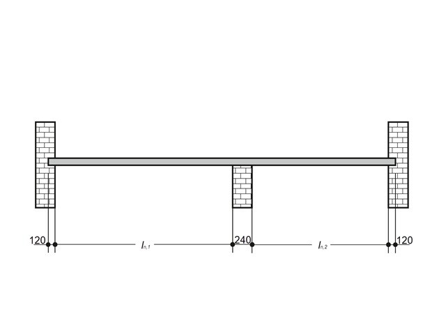
A reinforced concrete slab inside a building is to be designed as a 1.0 m stripe with members. The floor slab is uniaxially spanned and runs through two spans. The slab is fixed on masonry walls with free-rotating supports. The middle support has a width of 240 mm and the two edge supports have a width of 120 mm. The two spans are subjected to an imposed load of category C: congregation areas.
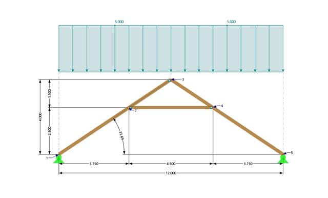
A collar beam roof with the selected geometry is compared in terms of its internal forces between the calculation using RFEM 6 and the manual calculation. In total, three load systems are analyzed.
Time history analysis of a cantilever beam (SDOF system) excited by a periodic function. Vertical deformations and accelerations calculated with direct integration and modal analysis in RF‑/DYNAM Pro - Forced Vibrations are compared with the analytical solution.
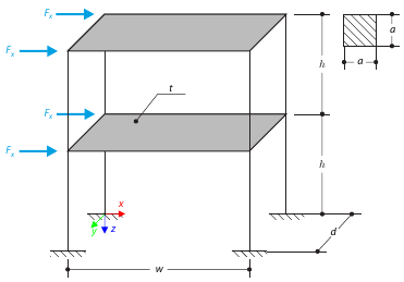
This example serves as a demonstration of the diaphragm constraint. The application is shown on a two-story structure. The structure is loaded by means of lateral forces according to Figure 1. Determine the maximum deflection of the structure ux in the direction of the loading forces using both the diaphragm constraint and the plate model of the floor.
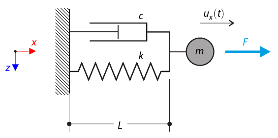
A single-mass system with dashpot is subjected to constant loading force. Determine the deflection and velocity of the dashpot endpoint in the given test time.
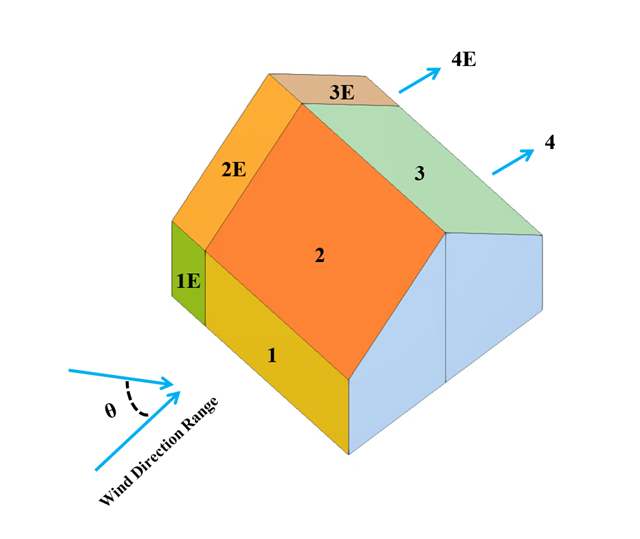
In the current validation example, we investigate wind pressure coefficient (Cp) for both main structural members (Cp,ave) and secondary structural members such as cladding or façade systems (Cp,local) based on NBC 2020 [1] and Japanese Wind Tunnel Data Base for low-rise building with 45 degree slope. The recommended setting for three-dimensional flat roof with sharp eaves will be described in the next part.

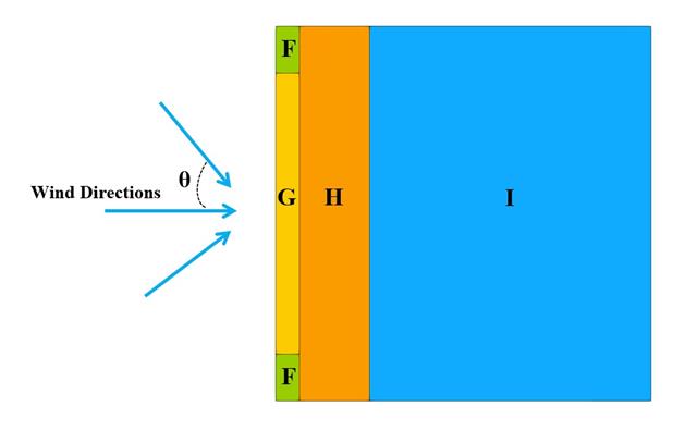
In the current validation example, we investigate wind pressure coefficient (Cp) of flat roof and walls with ASCE7-22 [1]. In the section 28.3 (Wind loads - main wind force resisting system) and Figure 28.3-1 (load case 1), there is a table which shows Cp value for different roof angle.

In this verification example, the capacity design values of shear forces on beams are calculated in accordance with EN 1998-1, 5.4.2.2 and 5.5.2.1 as well as the capacity design values of columns in flexure in accordance with 5.2.3.3(2). The system consists of a two span reinforced concrete beam with a span length of 5.50m. The beam is part of a frame system. The results obtained are compared with those in [1].
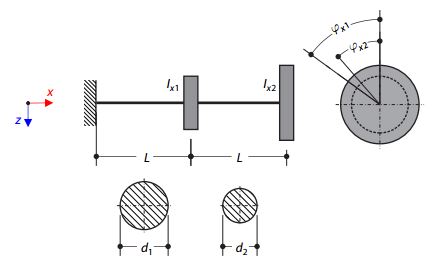
A double‑mass system consists of two shafts and two masses represented by the corresponding moments of inertia, concentrated in a given distance as nodal masses. The left shaft is fixed, and the right mass is free. Neglecting the self‑weight of the shafts, determine the torsional natural frequencies of the system.
In the current validation example, we investigate wind pressure value for both general structural design (Cp,10) and local structural design such as cladding or façade systems (Cp,1) based on EN 1991-1-4 flat roof example [1] and Japanese Wind Tunnel Data Base . The recommended setting for three-dimensional flat roof with sharp eaves will be described in the next part.

An inner column in the first floor of a three-story building is designed. The column is monolithic connected with the top and bottom beams. The fire design simplified method A for columns according to EC2-1-2 is than proofed and the results compared to [1].
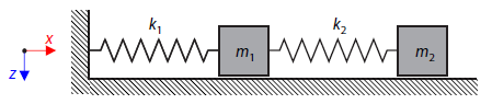
A double-mass oscillator consists of two linear springs and masses, which are concentrated at the nodes. The self-weight of the springs is neglected. Determine the natural frequencies of the system.

The model is based on the example 4 of [1]: Point-supported slab.
The flat slab of an office building with crack-sensitive lightweight walls is to be designed. Inner, border and corner panels are to be investigated. The columns and the flat slab are monolithically joined. The edge and corner columns are placed flush with the edge of the slab. The axes of the columns form a square grid. It is a rigid system (building stiffened with shear walls).
The office building has 5 floors with a floor height of 3.000 m. The environmental conditions to be assumed are defined as "closed interior spaces". There are predominantly static actions.
The focus of this example is to determine the slab moments and the required reinforcement above the columns under full load.