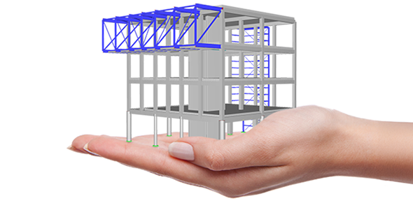
Nonlinear Material Behavior

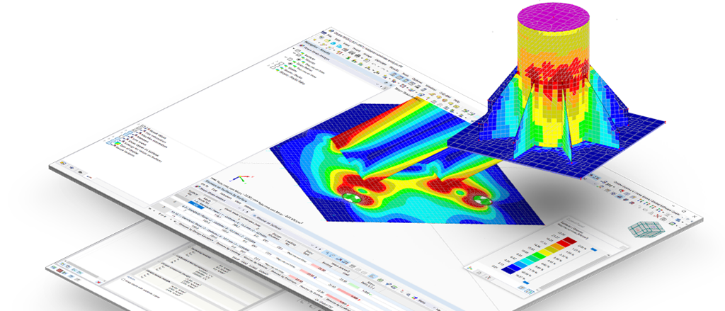
Considering Nonlinear Material Laws
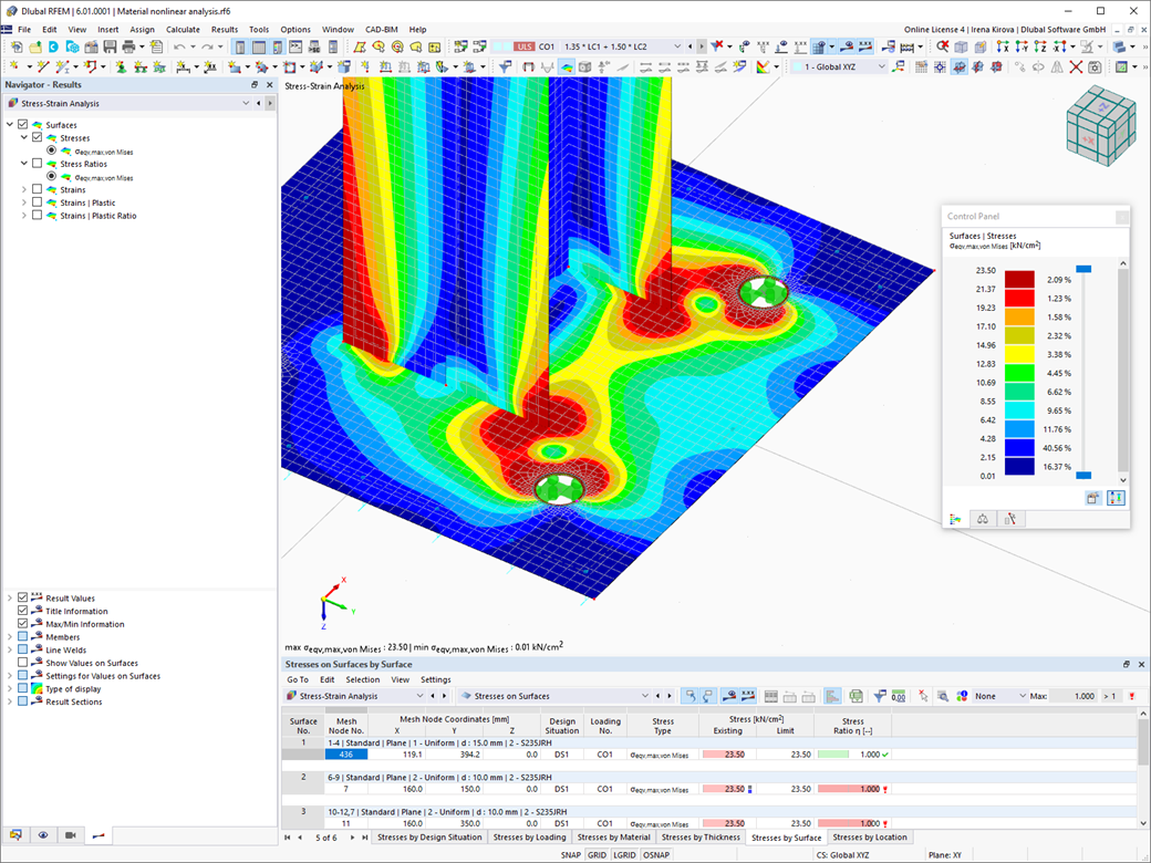
.png?mw=1040&hash=bc1654034a24ed3c4edafba4fc27e7e6f73b5bf0)
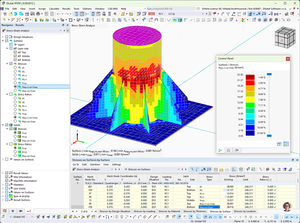
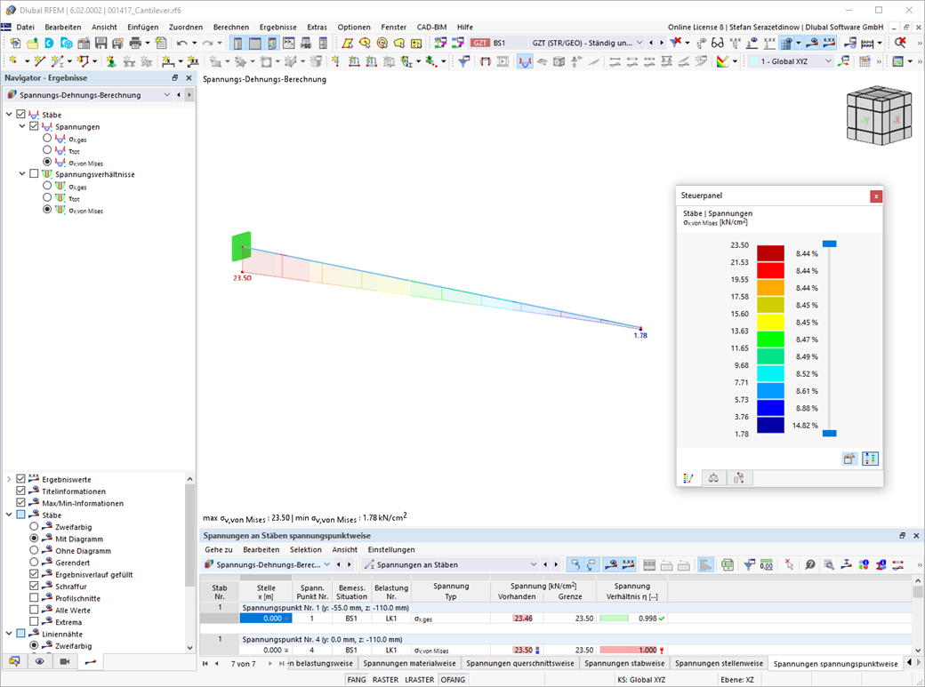
Nonlinear Material Behavior | Isotropic | Plastic (Members, Surfaces/Solids)
Did you know? When unloading the structural component with a plastic material model, in contrast to the Isotropic | Nonlinear Elastic material model, the strain remains after it has been completely unloaded.
You can select three different definition types:
- Standard (definition of the equivalent stress under which the material plastifies)
- Bilinear (definition of the equivalent stress and strain hardening modulus)
- Stress-strain diagram: definition of polygonal stress-strain diagram
- Option to save / import the diagram
- Interface with MS Excel
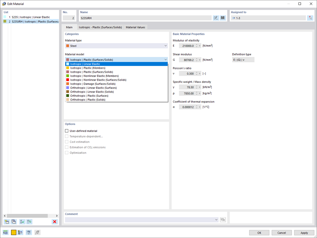
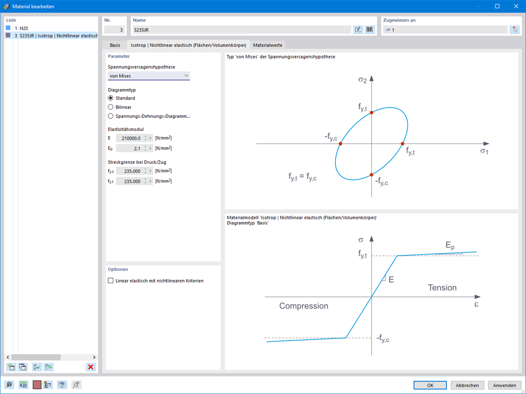
Nonlinear Material Behavior | Isotropic | Nonlinear Elastic (Members, Surfaces/Solids)
If you release a structural component with a nonlinear elastic material again, the strain goes back on the same path. In contrast to the Isotropic|Plastic material model, no strain is left when completely unloaded.
You can select three different definition types:
- Standard (definition of the equivalent stress under which the material plastifies)
- Bilinear (definition of the equivalent stress and strain hardening modulus)
- Stress-Strain Diagram:
- Definition of polygonal stress-strain diagram
- Option to save / import the diagram
- Interface with MS Excel
Background information about the orthotropic material model can be found in this technical article: Yield Laws in Isotropic Nonlinear Elastic Material Model .
.png?mw=1040&hash=8439f03288336aa43d74ff134d244188196c76e6)
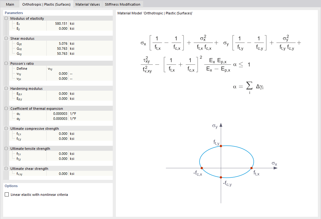
Nonlinear Material Behavior | Orthotropic | Plastic (Surfaces, Solids) | Tsai-Wu
Are you familiar with the Tsai-Wu material model? It combines plastic and orthotropic properties, which allows for special modeling of materials with anisotropic characteristics, such as fiber-reinforced plastics or timber.
If the material is plastified, the stresses remain constant. The redistribution is carried out according to the stiffnesses available in the individual directions. The elastic area corresponds to the Orthotropic | Linear Elastic (Solids) material model. For the plastic area, the yielding according to Tsai-Wu applies:
All strengths are defined positively. You can imagine the stress criterion as an elliptical surface within a six-dimensional space of stresses. If one of the three stress components is applied as a constant value, the surface can be projected onto a three-dimensional stress space.
If the value for fy(σ), according to the Tsai-Wu equation, plane stress condition, is smaller than 1, the stresses are in the elastic zone. The plastic area is reached as soon as fy (σ) = 1; values greater than 1 are not allowed. The model behavior is ideal-plastic, which means there is no stiffening.
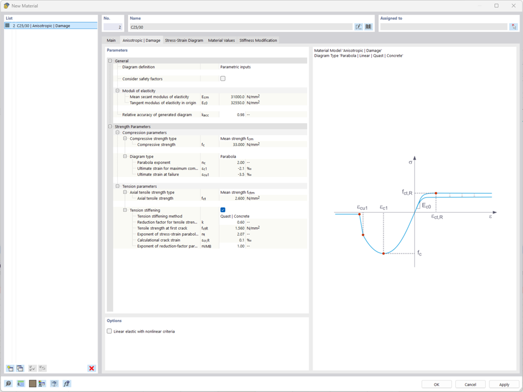
Nonlinear Material Model for Reinforced Concrete
The "Nonlinear Material Behavior" add-on includes the Isotropic | Anistropic Damage material model for concrete structural components. This material model allows you to consider concrete damage for members (also the "Rib" member type), surfaces, and solids.
You can define an individual stress-strain diagram via a table, use the parametric input to generate the stress-strain diagram, or use the predefined parameters from the standards. Furthermore, it is possible to consider the tension stiffening effect.
For the reinforcement, both nonlinear material models "Isotropic | Plastic (Members)" and "Isotropic | Nonlinear Elastic (Members)" are available.
It is possible to consider the long-term effects due to creep and shrinkage using the "Static Analysis | Creep & Shrinkage (Linear)" analysis type that has been recently released. Creep is taken into account by stretching the stress-strain diagram of the concrete using the factor (1+phi), and shrinkage is taken into account as the pre-strain of the concrete. More detailed time step analyses are possible using the "Time-Dependent Analysis (TDA)" add-on.
For nonlinear concrete design, the following surface results are available:
- Reinforcement results by surface reinforcement
- Concrete stresses
- Reinforcement stresses
- Concrete strains
- Reinforcement strains
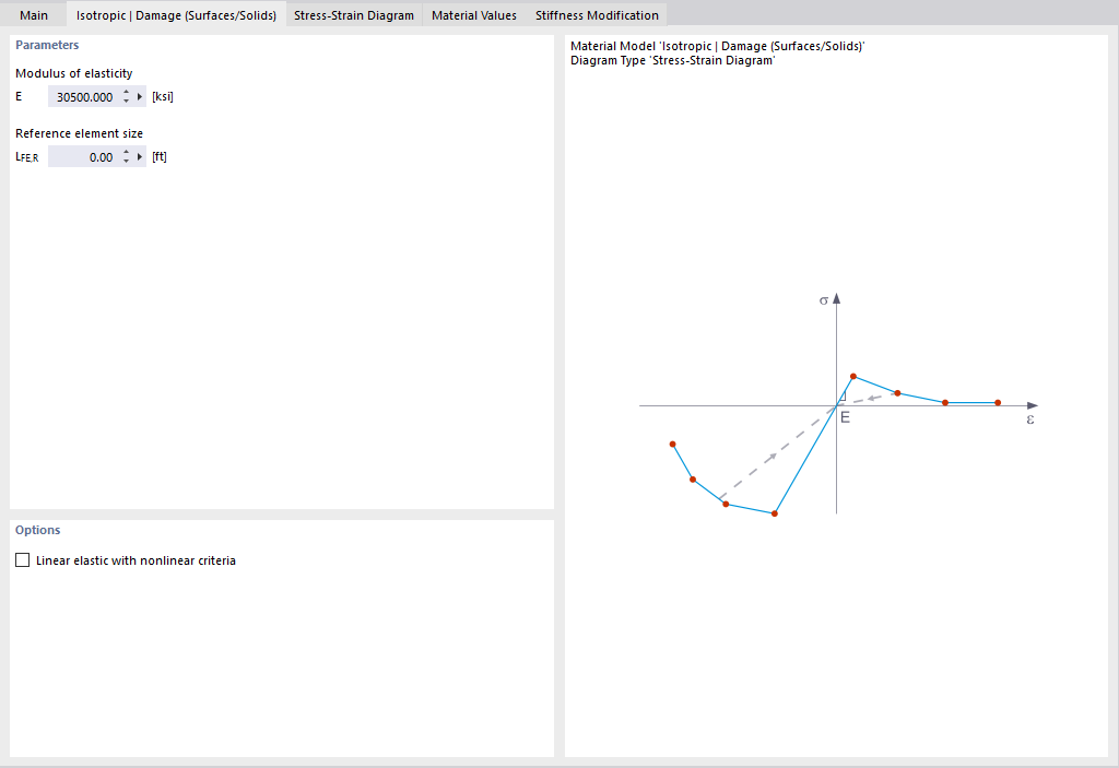
Nonlinear Material Behavior | Isotropic | Damage (Surfaces/Solids)
Did you already know? Unlike other material models, the stress-strain diagram for this material model is not anti-metric with respect to the origin. You can use this material model, for example, to simulate the behavior of steel fiber-reinforced concrete. For detailed notes on modeling steel fiber-reinforced concrete, see the technical article: KB | Determining Material Properties of Steel Fiber-Reinforced Concrete and Their Application in RFEM
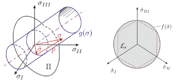
In this material model, the isotropic stiffness is reduced by a scalar damage parameter. This damage parameter is determined by the stress distribution defined in the diagram. The direction of the principal stresses is not taken into account; rather, damage occurs in the direction of the reference strain, which also encompasses the third direction perpendicular to the plane. The tension and compression areas of the stress tensor are treated separately, with different damage parameters applying to each.
The “reference element size” controls how the strain in the crack region is scaled to the length of the element. With the default value of zero, no scaling occurs. This ensures that the material behavior of steel fiber-reinforced concrete is close to reality in terms of modeling.
You can read the theoretical background on the “Isotropic Damage” material model in the technical article: KB 001461 │ Nonlinear Material Model Damage .
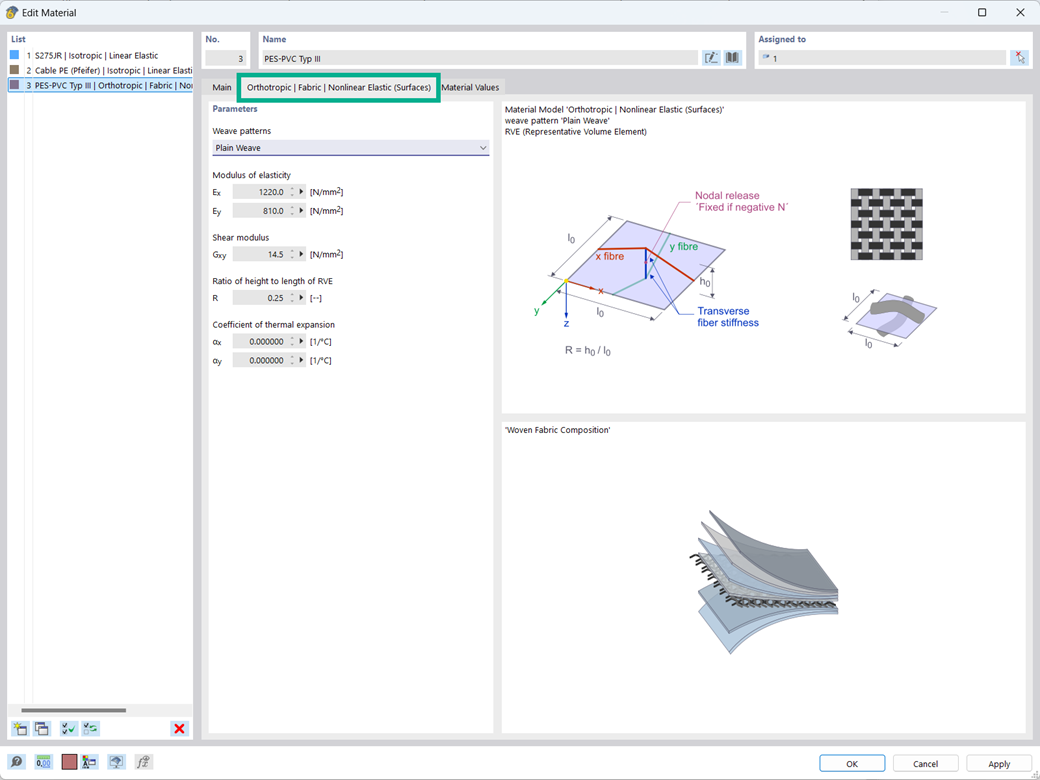
Nonlinear Material Behavior | Orthotropic | Fabric | Nonlinear Elastic (Surfaces)
The "Orthotropic | Fabric | Nonlinear Elastic (Surfaces)" material model allows you to define prestressed fabric membranes using the representative microstructure-solid element model – RVE.
By considering the fabric geometry in the microstructure model, the corresponding transversal strain effect can now be considered for all force conditions in the membrane.
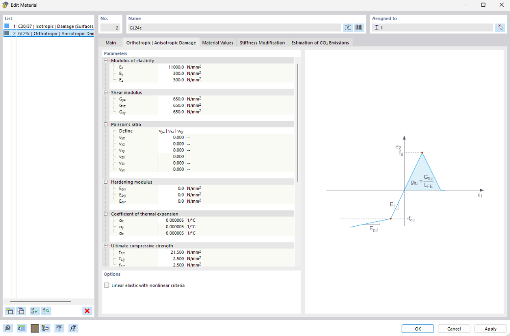
Nonlinear Material Behavior | Orthotropic | Anisotropic Damage
The “Orthotropic | Anisotropic Damage” material model combines plastic and fracture mechanics approaches, enabling specialized modeling of brittle materials with anisotropic properties, such as timber or fiber-reinforced concrete.
During plastic deformation of the material, the stresses remain constant. A redistribution of stresses occurs depending on the stiffnesses present in the individual directions. The elastic range corresponds to the “Orthotropic | Linear Elastic (Solid)” material model. Once the fractional mechanical properties are reached, a prediction of the resulting cracks is made.
The crack analysis is performed via a smeared crack using the finite element method. When a failure criterion is met, the corresponding stiffness is progressively reduced until it approaches zero. This allows for the precise determination of whether a crack forms and how it propagates.

.png?mw=200&hash=ceabdac71454991b172d1a40faa3844b9a756ff1)
Calculate Your Price