


Do you have any questions about Dlubal products or need assistance in selecting the right one for your project?
I'm here to help. You can easily reach me through the contact options provided below.
Looking forward to hearing from you!


Design of Steel Members According to American Standard ANSI/AISC 360


RF-/STEEL AISC | Features
- Design of members and sets of members for tension, compression, bending, shear, combined internal forces, and torsion
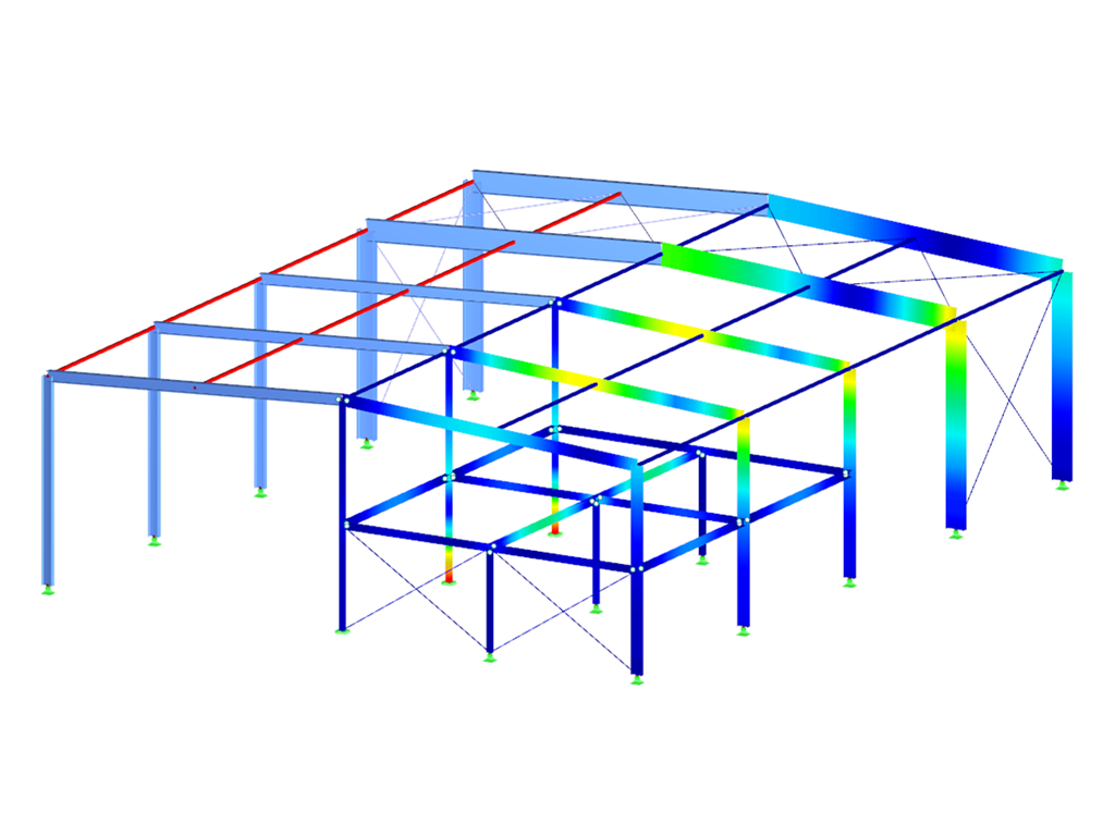
- Stability analysis of buckling and lateral-torsional buckling
- Automatic determination of critical buckling loads and critical buckling moments for general load applications and support conditions by means of a special FEA program (eigenvalue analysis) integrated in the module
- Alternative analytical calculation of the critical buckling moment for standard situations
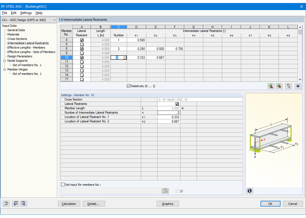
- Optional application of discrete lateral supports to beams and continuous members
- Automatic cross-section classification (compact, noncompact, and slender)
- Serviceability limit state design (deflection)
- Cross-section optimization
- A wide range of available cross-sections, such as rolled I-sections; channel sections; T-sections; angles; rectangular and circular hollow sections; round bars; symmetrical and asymmetrical, parametric I-, T-, and angle sections; double angles
- Clearly arranged input and result windows
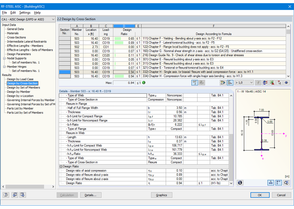
- Detailed result documentation including references to design equations of the used standard
- Various filter and sorting options of results, including result lists by member, cross-sections, and x-location, or by load case, load combination, and result combination
- Result table of member slenderness and governing internal forces
- Parts list with weight and solid specifications
- Seamless integration in RFEM/RSTAB
- Metric and imperial units
Working with RF-/STEEL AISC
First, it is necessary to decide whether to perform design according to ASD or LRFD. Then, you can enter the load cases, load combinations, and result combinations to be designed. Load combinations according to ASCE 7 can be generated either manually or automatically in RFEM/RSTAB.
In the next steps, you can adjust presettings of lateral intermediate supports, effective lengths, and other standard-specific design parameters, such as the modification factor Cb for lateral-torsional buckling or the shear lag factor. In the case of continuous members, it is possible to define individual support conditions and eccentricities of each intermediate node of single members. A special FEA tool determines critical loads and moments required for the stability analysis.
In connection with RFEM/RSTAB, it is possible to apply the Direct Analysis Method taking into account the influence of the general calculation according to the second-order analysis. In this way, you avoid using special enlargement factors.
RF-/STEEL AISC | Output of Results
The first result window shows the maximum design ratios with the corresponding design of each designed load case, load combination, or result combination.
The other result windows list all detailed results sorted by specific subject in extendable tree menus. All intermediate results along the members can be displayed at any location. In this way, you can easily retrace how the module has performed the individual designs.
The complete module data are part of the RFEM/RSTAB printout report. You can select the report contents and extent specifically for the individual designs.

.png?mw=192&hash=f63e4a3f1836233005de32f60201d5392e507cf1)
Webshop
Customize your individual program package and find out all the prices online!
Calculate Your Price

The price is valid for United States.


