


Answer:
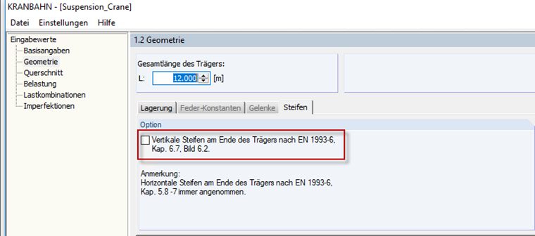
When defining the beam geometry in Window 1.2, the "vertical stiffeners at the end of the girder" option is activated by default in the "Stiffener" tab. Proceed as follows:
- In Window 1.2, open the "Stiffener" tab and deactivate the option (Image 01).
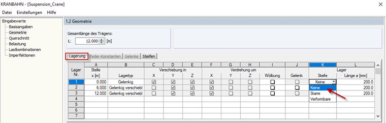
- Now, you can deactivate the stiffeners in Column K in the "Supports" tab (Image 02).
- In Window 1.4 "Loads", the girder buffers can now be deactivated (Image 03).
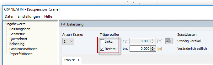
The suspension crane can go beyond the girder ends now.