The structural analysis software RFEM 6 is the basis of a modular software system. The main program RFEM 6 is used to define structures, materials, and loads of planar and spatial structural systems consisting of plates, walls, shells, and members. The program also allows you to create combined structures as well as to model solid and contact elements.
RSTAB 9 is a powerful analysis and design software for 3D beam, frame, or truss structure calculations, reflecting the current state of the art and helping structural engineers meet requirements in modern civil engineering.
Do you often spend too long calculating cross-sections? Dlubal Software and the RSECTION stand-alone program facilitate your work by determining section properties of various cross-sections and performing a subsequent stress analysis.
Do you always know where the wind is blowing from? From the direction of innovation, of course! With RWIND 2, you have a program at your side that uses a digital wind tunnel for the numerical simulation of wind flows. The program simulates these flows around any building geometry and determines the wind loads on the surfaces.
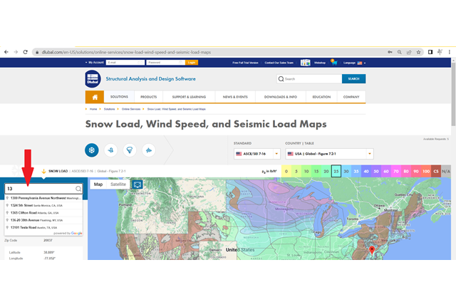
Are you looking for an overview of snow load zones, wind zones, and seismic zones? Then you are in the right place. Use the Geo-Zone Tool to determine quickly and efficiently snow loads, wind speeds, and seismic data according to ASCE 7‑16 and other international standards.
Would you like to try out the capabilities of the Dlubal Software programs? You have the opportunity to do so! The free 90-day full version allows you to thoroughly test all our programs.
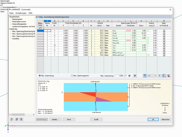
Generally, the module assumes that there is a rigid coupling between the layers.
More information about calculation with the RF‑LAMINATE add-on module can be found in the respective manual. This also explains the special features of various material models (isotropic, orthotropic, and hybrid).
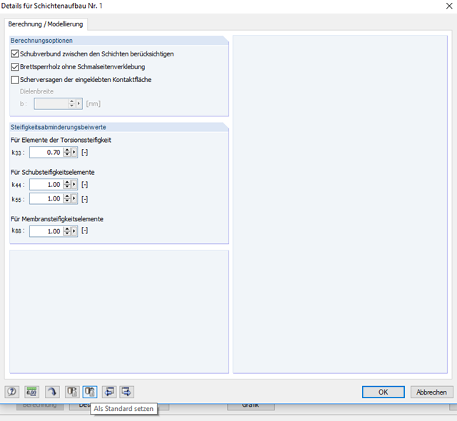
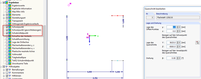
The activated option for glue at narrow sides generally relates to the design of cross-laminated timber surfaces. However, the RF‑LAMINATE add-on module is also suitable for other materials, such as carbon fibers, plastics, and laminated glass. Therefore, this setting cannot be set by default. However, it is possible to define this as a default setting (Image 01).
The reason is that the effective lengths or buckling lengths of the members and sets of members are different. While the actual length is used for the stability analysis in the case of members, the length of the summarized members is used in the case of sets of members.
Example
The frame shown in Image 01 consists of a horizontal beam that is divided into four equally long members. Furthermore, a set of members is created for the four members. The stability analysis is performed according to the equivalent member method for both cases.
For the member design, the program calculates with a length of 1.00 m in each case. In contrast, the set of members has a length of 4.00 m (see Image 02). This difference in length certainly affects the stability design, which means that the design ratios are also different (see Image 03).
In addition, we do not recommend calculating all members and sets of members in a single design case, because this leads to falsified results.