The structural analysis software RFEM 6 is the basis of a modular software system. The main program RFEM 6 is used to define structures, materials, and loads of planar and spatial structural systems consisting of plates, walls, shells, and members. The program also allows you to create combined structures as well as to model solid and contact elements.
RSTAB 9 is a powerful analysis and design software for 3D beam, frame, or truss structure calculations, reflecting the current state of the art and helping structural engineers meet requirements in modern civil engineering.
Do you often spend too long calculating cross-sections? Dlubal Software and the RSECTION stand-alone program facilitate your work by determining section properties of various cross-sections and performing a subsequent stress analysis.
Do you always know where the wind is blowing from? From the direction of innovation, of course! With RWIND 2, you have a program at your side that uses a digital wind tunnel for the numerical simulation of wind flows. The program simulates these flows around any building geometry and determines the wind loads on the surfaces.
Are you looking for an overview of snow load zones, wind zones, and seismic zones? Then you are in the right place. Use the Geo-Zone Tool to determine quickly and efficiently snow loads, wind speeds, and seismic data according to ASCE 7‑16 and other international standards.
Would you like to try out the capabilities of the Dlubal Software programs? You have the opportunity to do so! The free 90-day full version allows you to thoroughly test all our programs.
The Tower Design add-on is still under development. Therefore, it cannot be activated in the Base Data.
No, the module isn't implemented in RFEM 6 / RSTAB 9 just yet. It's still in development right now.
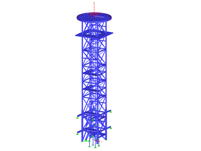
For open structures that consist only of members, such as lattice towers, the load acts only on the member cross-sections.
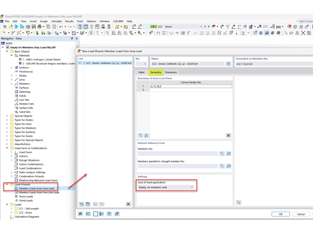
To apply area loads such as snow or wind to an open structure, select Load Wizards → Member Loads from Area load to create a new area load. Under the Geometry tab, select "Empty, on members only" for the Area of load application.
The area load can be displayed on individual members by right-clicking the load and selecting Display separately.
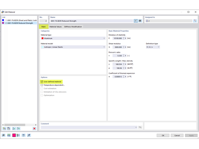
The weld-affected zone strengths listed in the Material Values are currently not being considered by the program. The weld design is being developed and will be considered in the future.
Below are the steps to consider the reduced strengths:
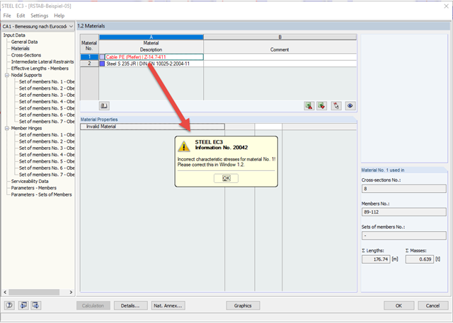
1) Activate the User-defined material option (Image 01)
2) In the Material Values tab, re-enter the weld-affected zones strengths in the standard strengths (Image 02)
3) To consider the weld-affected zone strengths only at the end of the members, divide the member into smaller segments and assign the applicable materials (Image 03)
4) To keep the divided members as one continuous member, select all the members and right-click to Create Member Set (Image 04)
Where the geometries become complicated, it is difficult to use analytical methods for the design. The weld elements in RFEM 6 are particularly helpful for such applications.
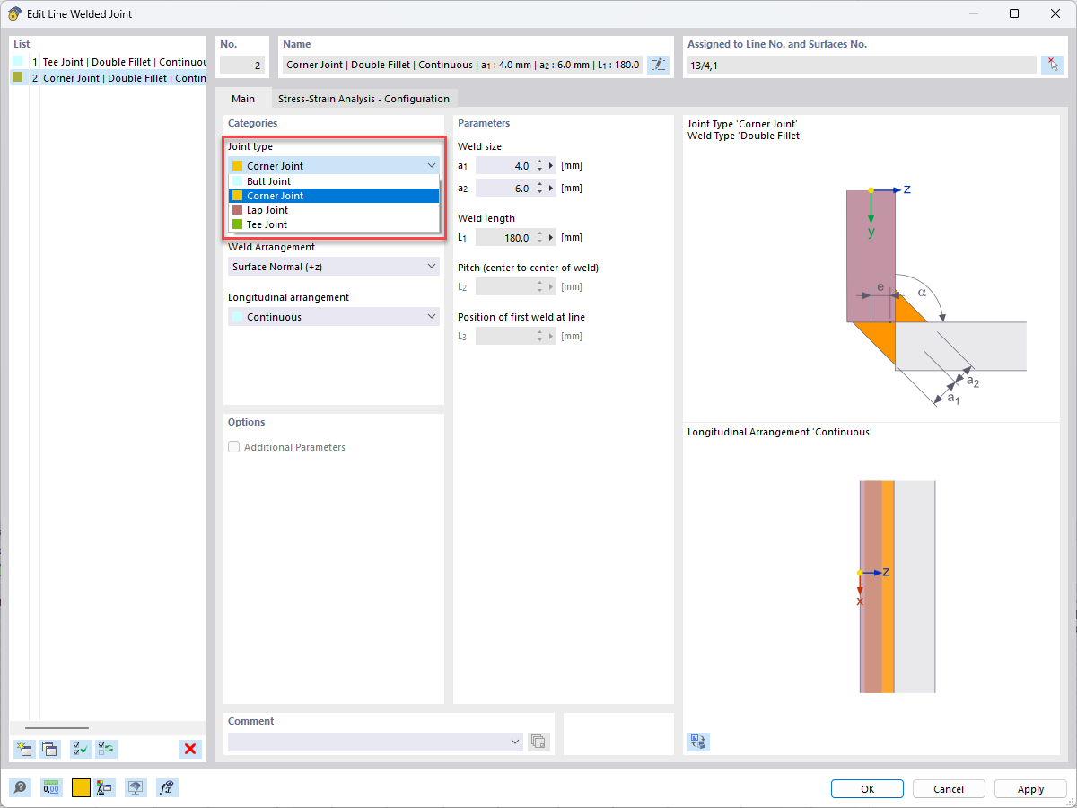
RFEM 6 allows for design checks for different types of welds.
In the Joint type list, you can select how the surfaces to be connected are related to each other.
Then, select a weld type.
Finally, it is necessary to define the weld parameters.
The welds do not affect the stiffness of the model. You use the stresses from the surface elements and evaluate them according to the regulations.
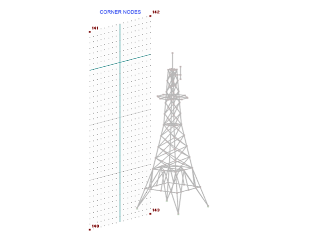
1. Define a plane that will be used to apply the load. You can do so by creating 4 corner nodes around your structure (Image 01).
2. Go to Insert→ Load Wizards→ Member Loads from Area Loads. Specify the direction and magnitude in the Main tab (Image 02).
3. Select the Geometry tab and select the corner nodes that were previously created. (Image 03).
4. Select the Tolerances tab and enter a distance that will capture the entire width/height of the structure (Image 04). Click OK to exit.
5. Right click on the area load and select Display separately. The area load is now displayed as member loads (Image 05).
1. Define a plane that will be used to apply the wind load. You can do so by creating 4 corner nodes around your structure (Image 01).
2. Go to Tools → Generate Loads → From Area Loads on Members via Planes. Define the direction, magnitude, and Select Empty, On Members Only (Image 02). Select the corner nodes that were previously created.
3. Select Settings for load generation to adjust the tolerance type. Select Absolute via distance and enter a value that will capture the entire width/length of the structure (Image 03). Click OK twice to exit.
4. Right click on the area load and select Display Separately (Image 04). The area load is now displayed as member loads (Image 05).
Note: The applied load is based on the member orientation.
Yes, this is generally possible.
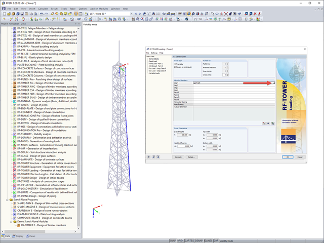
If a tower structure exported from RF‑/TOWER is recognized, all model-relevant members of this add-on module are listed in the Allocated Members section. Here, you can also find the member numbers of the objects defined in RF‑/TOWER Equipment.
If the model was created without RF‑/TOWER Structure, the member numbers can be entered manually in the table rows. You can also use the button to define the components graphically in the work window of RFEM or RSTAB.