The structural analysis software RFEM 6 is the basis of a modular software system. The main program RFEM 6 is used to define structures, materials, and loads of planar and spatial structural systems consisting of plates, walls, shells, and members. The program also allows you to create combined structures as well as to model solid and contact elements.
RSTAB 9 is a powerful analysis and design software for 3D beam, frame, or truss structure calculations, reflecting the current state of the art and helping structural engineers meet requirements in modern civil engineering.
Do you often spend too long calculating cross-sections? Dlubal Software and the RSECTION stand-alone program facilitate your work by determining section properties of various cross-sections and performing a subsequent stress analysis.
Do you always know where the wind is blowing from? From the direction of innovation, of course! With RWIND 2, you have a program at your side that uses a digital wind tunnel for the numerical simulation of wind flows. The program simulates these flows around any building geometry and determines the wind loads on the surfaces.
Are you looking for an overview of snow load zones, wind zones, and seismic zones? Then you are in the right place. Use the Geo-Zone Tool to determine quickly and efficiently snow loads, wind speeds, and seismic data according to ASCE 7‑16 and other international standards.
Would you like to try out the capabilities of the Dlubal Software programs? You have the opportunity to do so! The free 90-day full version allows you to thoroughly test all our programs.
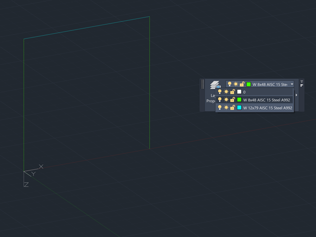
The naming of layers in AutoCAD can be used to map sections and materials to centerlines that are connecting in your model. Make sure all of the same sections and materials are grouped together in a layer for each center line. Next, open RFEM 6 and navigate to the Import options under the File menu and select AutoCAD. A new dialog box will appear and here select the options "Use layer identification" and "Generate members".Click "OK" and then a new dialog box will appear called "Conversion Tables". This is where the name of the Layer from AutoCAD is linked with the material and section in RFEM. There are two tabs, the first is for Materials and the second is for Sections. Under the materials tab for example, in the left column the exact name of the Layer in AutoCAD must be typed and then in the right column there is a button with 3 dots in the cell. Press this button and the material library will appear. Select the material and then this will be applied to the lines associated with the linked Layer.After linking materials and sections, click "OK" and then one last dialog box will appear giving details on the imported model. Click "OK" and then you will see the model with mapped materials and sections.