The structural analysis software RFEM 6 is the basis of a modular software system. The main program RFEM 6 is used to define structures, materials, and loads of planar and spatial structural systems consisting of plates, walls, shells, and members. The program also allows you to create combined structures as well as to model solid and contact elements.
RSTAB 9 is a powerful analysis and design software for 3D beam, frame, or truss structure calculations, reflecting the current state of the art and helping structural engineers meet requirements in modern civil engineering.
Do you often spend too long calculating cross-sections? Dlubal Software and the RSECTION stand-alone program facilitate your work by determining section properties of various cross-sections and performing a subsequent stress analysis.
Do you always know where the wind is blowing from? From the direction of innovation, of course! With RWIND 2, you have a program at your side that uses a digital wind tunnel for the numerical simulation of wind flows. The program simulates these flows around any building geometry and determines the wind loads on the surfaces.
Are you looking for an overview of snow load zones, wind zones, and seismic zones? Then you are in the right place. Use the Geo-Zone Tool to determine quickly and efficiently snow loads, wind speeds, and seismic data according to ASCE 7‑16 and other international standards.
Would you like to try out the capabilities of the Dlubal Software programs? You have the opportunity to do so! The free 90-day full version allows you to thoroughly test all our programs.
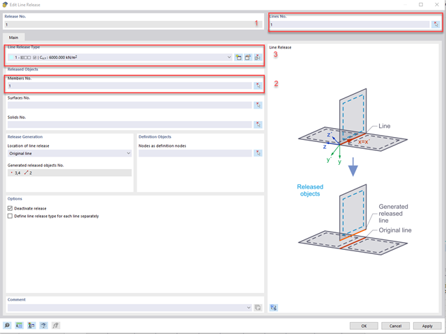
The stiffening can be modeled using line releases as follows:
Another option for applying stiffening is described in the following FAQ:
You can find another article on the subject of flexible timber joints on our website:
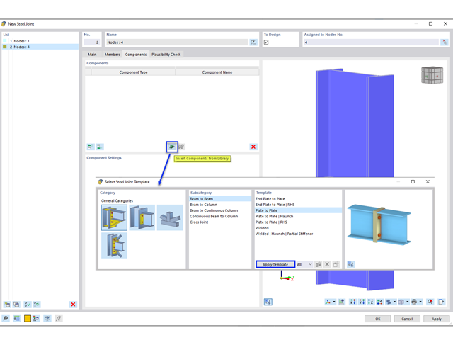
A splice connection using end plates can be easily created using the “Plate to Plate” template from the Components library (Image 01).
For a splice joint without end plates, the configuration can be created manually by adding individual components (Image 02).
The configuration includes the following components. Each component can be easily deleted or copied by right-clicking on the component.
It is required that a small gap is created using “Member Cut” and “Auxiliary Plane”. The gap is divided between the two members (that is, 1/16” gap is applied as 1/32” displacement to each member).
Alternatively, a sample model “AISC Splice Connection” can be downloaded and saved as a user-defined template (Image 03).
The CRANEWAY program can only design the main girders, not the bridge crane itself. The endcarriages of the bridge crane are also not designed.
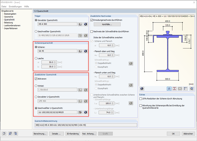
For an overhead crane, you can define the parameters of the rail cross-section as well as an additional cross-section in Window 1.3 of CRANEWAY.
For a splice, you can define the width a and the height b. Beam cross-sections made of rolled or welded sections can be combined with a rail or a splice. If the rail cross-section is too large or the girder cross-section is too small, you can only continue the entry with a plausible crane girder section.
Angled and channel cross-sections are possible as additional cross-sections. They can be selected as beam cross-sections in the [Library] or defined using the button.
On our website, you can find an interesting webinar about "Design of Craneway Girders According to Eurocode 3".