


Answer:
The stiffening can be modeled using line releases as follows:
- Create a line with the planned beam dimensions.
- Open the "Edit Line" dialog box and assign a member with the cross-section of the planned stiffening to the line.
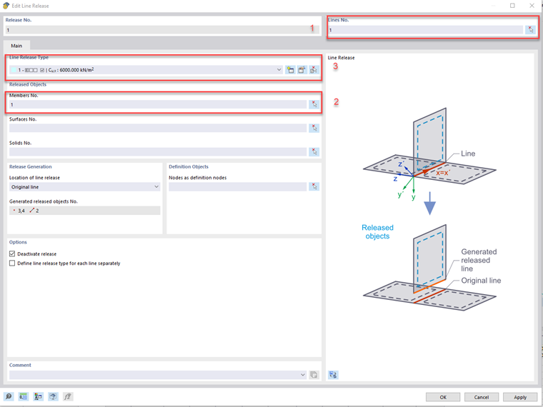
- Create a New Line Release in the "Special Objects" subfolder by right-clicking it.
- A dialog box appears where you can select the previously created line and then the created member (see the image).
- Create a new Line Release type and enter the appropriate support conditions in the dialog box according to your planned stiffening and fasteners.
- Select the original line and repeat Steps 2 through 5 to create a second reinforcement (for unsymmetric cross-sections, the corresponding section should be arranged with an angle of 180°).
- Assign the cross-section of the main beam to the original line.
- Now, you can assign a corresponding eccentricity to the stiffening beams.
Another option for applying stiffening is described in the following FAQ:
FAQ 4741 | How can I retroactively apply a reinforcement to a modeled downstand beam?You can find another article on the subject of flexible timber joints on our website:
KB | Considering Elastic Slip Modulus of Timber Connection