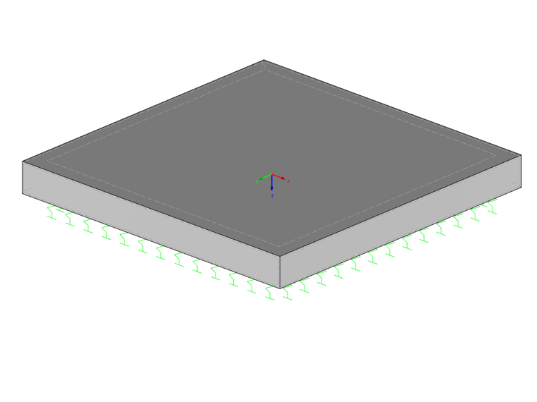
This support is represented by vertical springs, which are applied with constant spring stiffness and independent of each other. Therefore, it is not possible to calculate any subsidence basin close to reality. This type of foundation is also referred to as Winkler bedding. To apply this method, the bedding modulus ks (C1z in the program) is required, which is calculated on the basis of the soil pressure σ0 and the corresponding settlement s.
A disadvantage of the subgrade reaction modulus method is, among others, that the soil modeling is insufficient and the adjacent ground areas cannot be considered. Since the soil load causes the deformation directly only under the load itself, the subsidence basin does not reflect the reality. Shear stiffness of the soil is also not taken into account.
Subgrade Reaction Modulus Method with Variable Bedding Modulus
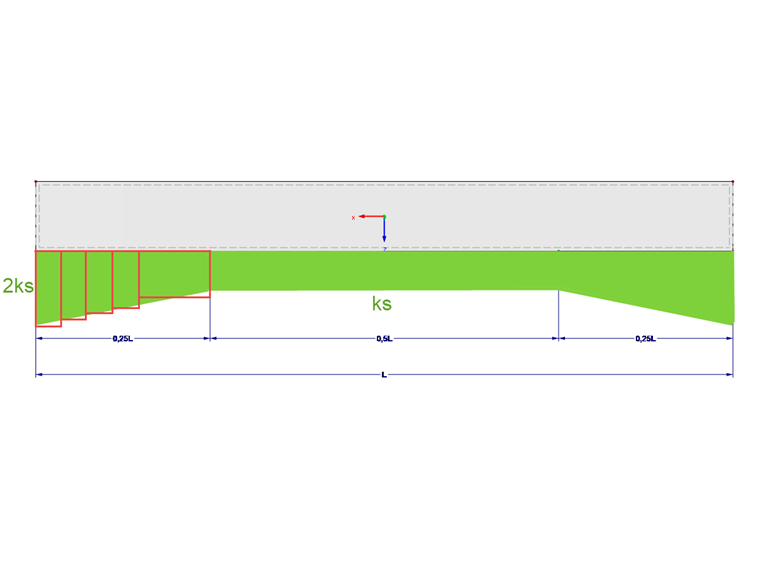
The deficiencies of the conventional subgrade reaction modulus method can be diminished by defining a variable bedding modulus. Dörken & Dehne [2] recommend a bedding modulus directed on the edge of a narrow strip rising up to twice the value. This should simulate the soil effects outside the foundation edge. The resulting settlements are significantly improved by this method.
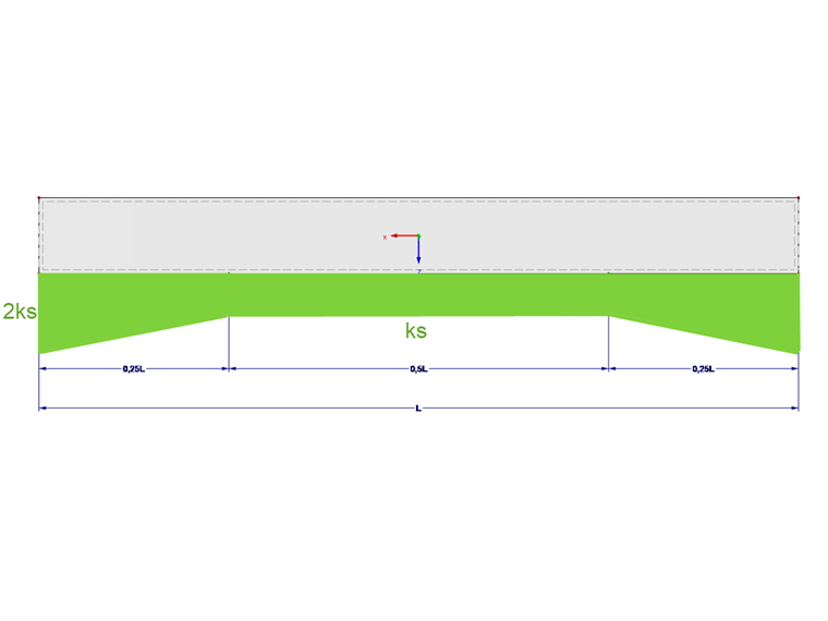
The variable bedding course can be entered in RFEM using a stepped edge area. However, some advantages of the conventional subgrade reaction modulus method, such as clear overview and fast program input, are lost in the case of this modeling.
Consideration of Adjacent Ground Areas Using Additional Springs
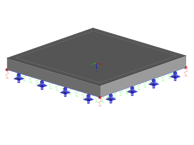
This model is based on the "Effective Soil Model" method by Kolář & Němec [3]. In contrast to the variable bedding modulus method, shear resistance is also considered in addition to the bedding modulus. The adjacent ground areas are taken into account using line springs and single springs on the edges.
The springs applied in our example result from the vertical bedding parameter of 54,500 kN/m³ as follows:
s0 represents the range of the subsidence basin in which the settlements drop below 1% of the foundation edge values. As a guiding value, a length of 0 m ≤ s0 ≤ 5 m can be assumed for slabs with a size of 5 m x 5 m up to 15 m x 30 m. For larger slabs installed on soils with high internal friction and cohesion as well as high shear moduli, values for s0 > 5 m can be applied.
cv,xz and cv,yz are the shear springs for the surface elastic foundation.
0.1 ∙ c1 < c2 < 1.0 ∙ c1
In the case of loose sand, c2 approaches zero; for solid rock types, however, it is 1.0 * c1. For medium shear capacity, c2 = 0.5 ∙ c1 is reasonable.
k represents the line spring along the outer edge of the foundation.
The factor K specifies the single springs in the edge areas of the foundation.
Since the shear resistance and the adjacent ground areas are considered in this variant, more realistic results are obtained. Another advantage in comparison with the previous variant is that the modeling is quite easy and it is not necessary to define any additional surfaces in the edge area.
Calculation in RF-SOILIN Add-on Module
However, you can obtain significantly more detailed soil properties using the stiffness modulus approach in the RF‑SOILIN add‑on module. Among other features, this program allows you to consider several soil layers and soil samples. Another advantage of using this add-on module is the realistic representation of interaction between a building and soil. RF-SOILIN determines the foundation properties automatically. Since this approach provides considerably more precise representation of the subsidence basin of a building, it is also possible to analyze the possible settlement effects on the adjacent buildings.
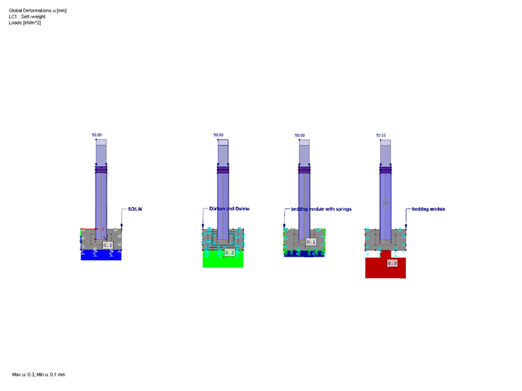
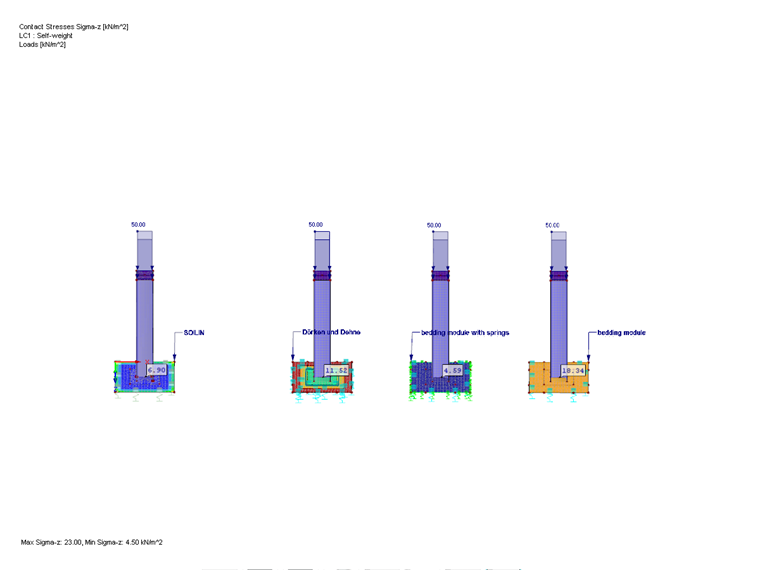
Comparison of Variants
The three calculation methods following the realistic approach increase the edge stiffness accordingly. Therefore, significantly better results are usually obtained. The example shows that contact stresses and deformations are different, depending on the method used. The more accurately the foundation properties are determined according to the individual methods, the better the contact stresses correspond to those determined in RF-SOILIN.
To compare the calculation variants, the results of the foundation properties from RF‑SOILIN were averaged in the neutral axis of the surface and applied to the other variants as a translational spring cuz.