


For this, a foundation plate with a cantilever beam is designed in RF‑FOUNDATION Pro. The design of the rotational displacement of the foundation (serviceability limit state design) is carried out for the first and the second core width. Subsequently, the results from RF‑FOUNDATION Pro will be compared to a surface model in RFEM.
Further geotechnical analyses and the design checks of the steel cantilever beam are not explained in this article.
System, Loads, and Support Forces
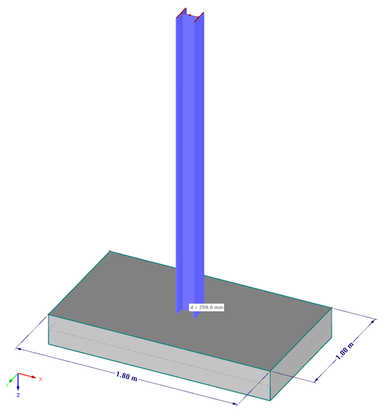
In this example, a steel cantilever beam (cross-section HEA 160, structural steel S235) with a length of 2.50 m is rigidly connected to a foundation plate.
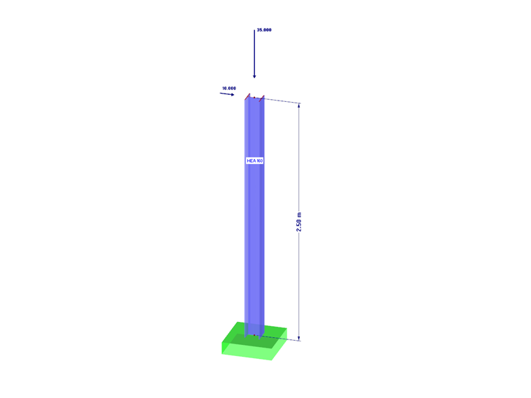
For this, a beam with a length of 2.50 m is modeled in RFEM. A rigid nodal support is arranged on this base point. The cantilever beam is subjected to vertical and horizontal forces on the column head. The load is entered in two load cases:
Load Case 1 = Self-weight
Load case 2 = Wind in + X
In Load Case 1, a vertical load of Gk = 35 kN is applied to the column head. Taking into account the self-weight of the column, the support force of Pz = 35.76 kN results in Load Case 1.
In Load Case 2, a horizontal force of Hk = 10 kN is applied to the column head. Thus, the resulting support force Px = 10.0 kN.
The foundation plate has the following dimensions:
Length L = 1.80 m
Width B = 1.00 m
Thickness t = 0.25 m
Combinations for Ultimate and Serviceability Limit State Design Checks
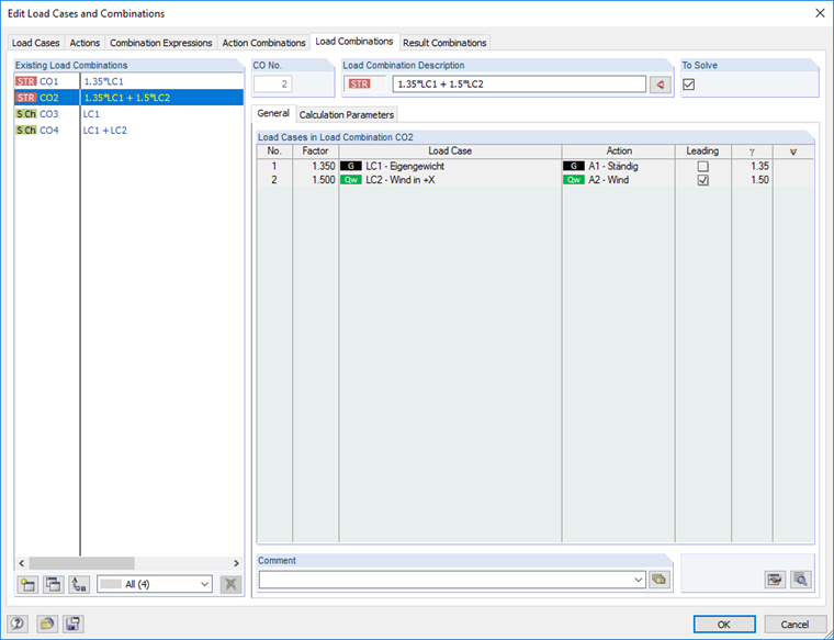
In RFEM, the following combinations are created for the ultimate and the serviceability limit state design checks:
Combination 1 (ULS) = 1.35 · G
Combination 2 (ULS) = 1.35 · G + 1.50 · Q
Combination 3 (SLS) = 1.00 · G
Combination 4 (SLS) = 1.00 · G + 1.00 · Q
ULS and SLS Design of Foundation
To design the foundation plate, a new case is created in RF‑FOUNDATION Pro. In the design details, all geotechnical design checks are deactivated except for the highly eccentric loading in the core.
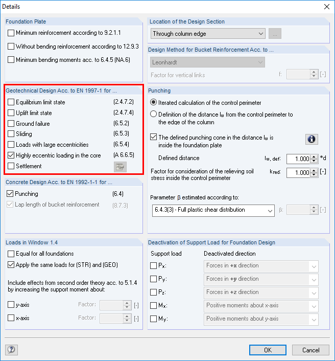
Due to these detailed settings (see Image 03), two tabs are available for entering loads in Window "1.4 Loading" of RF‑FOUNDATION Pro. CO 1 and CO 2 are selected for the design in the "Structural (STR) and Geotechnical (GEO)" tab. CO 3 and CO 4 are selected for the design in the "Characteristic Values" tab. The loads for the foundation rotation design are defined by selecting the loading in the "Characteristic Values" tab. In this case, the classification in "Permanent Action G" or "Permanent and Variable Action G + Q" must be respected.
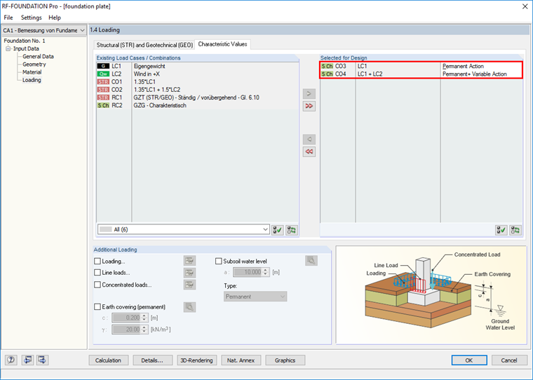
According to [2], no gaping joint may arise due to the characteristic loading of the permanent actions. This means: The ground pressure resultant must lie in the first core width. Due to the characteristic loading of the permanent and variable actions, the maximum of one gaping joint may arise up to the foundation center, or at least half the foundation base must be subjected to compression. This means: The ground pressure resultant must lie in the second core width.
The bending design of the foundation plate, which cannot be deactivated in RF‑FOUNDATION Pro and must always be performed, will not be discussed in the following text. Only the results of the highly eccentric loading in the core should be evaluated.
In this example, the design criterion of zero results for the first core width as the vertical load was only entered in LC1 (permanent load).
For the design of the second core width, the design criterion of 0.989 results.
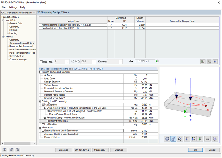
First, the resulting design moment is determined in the x-direction. To do this, the moment in the soil joint resulting from the foundation height and the amount of the support force Px is added to the support moment around the y-axis from RFEM:
MRes,x = 25.55 kNm + 0.25 m · 10 kN = 28.05 kNm
The characteristic value of the vertical force in the soil joint results from the governing column normal force and the self-weight of the foundation plate:
VRes = 35.76 kN + 1.80 m · 1.00 m · 0.25 m · 25.0 kN/m³ = 47.01 kN
Accordingly, the resulting eccentricity ex in the x-direction is calculated as follows:
Since the load in the y-direction is zero in this example, the eccentricity in the y-direction is also zero.
The design of the second core width gives the result:
The design criterion results in:
The calculated result values are summarized in Result Window "2.2 Governing Design Criteria" of RF‑FOUNDATION Pro. For this, see the following graphic.
Checking Soil Contact Stresses in RFEM
The foundation plate dimensions designed in RF‑FOUNDATION Pro can optionally be checked in RFEM now. For this, a check can be made to ascertain whether the gaping joint forms at maximum up to the foundation plate center, as described in [2], Paragraph 3.4 under "Geotechnics."
First, an RFEM model is created where the rigid nodal support is replaced by a foundation plate. The foundation plate has exactly the same dimensions as the single foundation, with a design criterion of 0.989 designed in RF‑FOUNDATION Pro with regard to the foundation rotation.
The entered foundation plate must have a surface support in RFEM. In this case, it should be noted that this surface support should be defined with values for the spring in the z-direction that are close to reality. The "rigid" setting in the z-direction is not effective here.
Optionally, the spring stiffness of the nodal support can be determined when specifying the soil profile in RF‑FOUNDATION Pro. Then, you can convert and set this spring stiffness for the single foundation in the spring stiffness for a surface support.
After the calculation, "Contact Stresses σZ" can be displayed for the CO that governs for the foundation rotation design in RFEM under the results. Furthermore, the range of values for displaying results in the result panel can be adjusted in such a way that only the contact stresses > 0 kN/m² are displayed. This setting allows you to check graphically up to which location of the foundation the gaping joint arises. The following graphic shows the contact stresses σZ for CO 4.
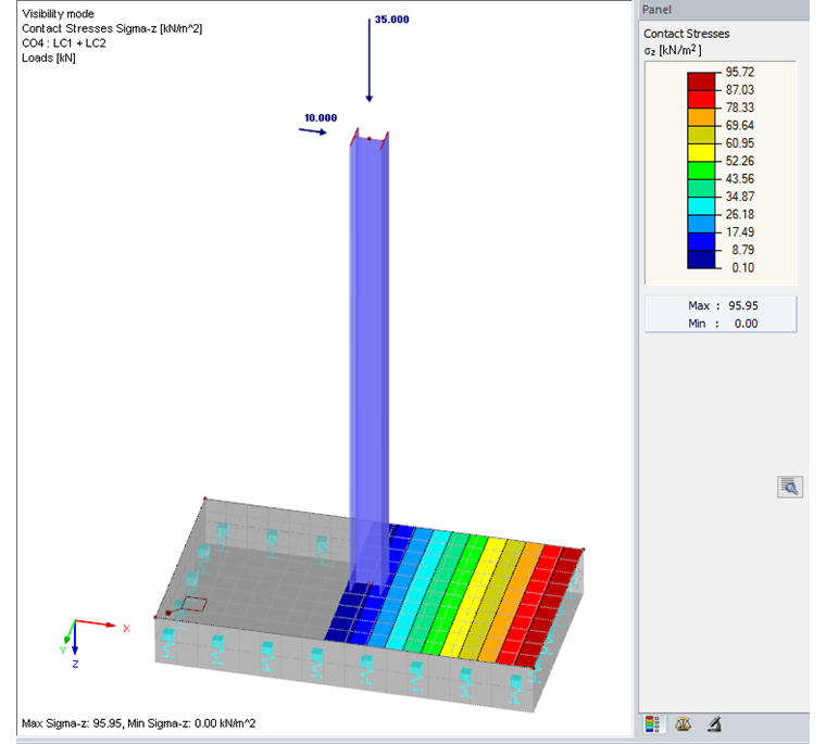
It is obvious here that the gaping joint goes almost to the center of the foundation. This is also confirmed by the result from RF‑FOUNDATION Pro and the resulting design criterion for the foundation rotation design.
The model for this article was created in RFEM 5 using RF‑FOUNDATION Pro. The design of highly eccentric loading in the core according to DIN EN 1997‑1 is also included in FOUNDATION Pro for RSTAB 8 in the same form, of course. The only difference is that the surface model of the foundation plate cannot be created in RSTAB in this form.
In RSTAB 8, this situation can be simulated as uniaxial loading (as shown in this example). To do this, the foundation can be modeled using a beam with an elastic foundation (beam member). The beam can be provided with a member elastic foundation "Failure if negative contact stresses".