In many cases, the effective length may be taken as half of the member length (0.5L) for both in-plane and out-of-plane of concentrically loaded compression braces in X-braced frames, as stated in Appendix 7 of AISC 360-16. The braces shall have identical cross-sections with similar compression and tension forces and are attached at the midpoint [1].
Additionally, AISC allows the effective length to be taken as half of the member length when the members are not expected to undergo large, cyclic inelastic deformations and the seismic response modification coefficient, R, is equal to 3 or less [2].
Larger unbraced lengths for out-of-plane buckling may be required for X-braced frames with unbalanced brace forces, especially those with continuous midpoint connections [1]. Using half of the length of the member may also be unsuitable when considering bracing in a seismic force resisting system (SFRS) that is expected to undergo large, cyclic, inelastic deformations. As an example, X-bracings as part of specially concentrically braced frames (SCBF) should use the full length of the member [2].
Example
The example in this article assumes that the effective length of the steel X-bracings can be taken as half the length of the member. Two options to define the effective length are presented for comparison.
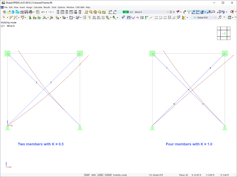
In the Main tab of the Effective Lengths dialog box, the user can select the required buckling checks and other relevant factors (Image 1).
In the Nodal Supports & Effective Lengths tab, the effective length factors, K, can be adjusted.
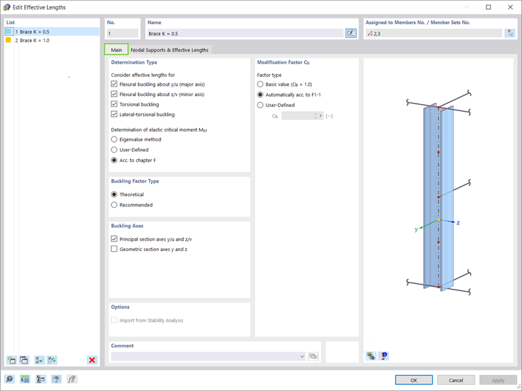
The first option is to keep the X-braces as full length (Image 2). The Effective Length Factors option must be used here, since the center node to assign the nodal support does not exist. The effective length factor, K, is set to 0.5 to consider half the length of the member. The k factor used here is irrelevant to the member end condition.
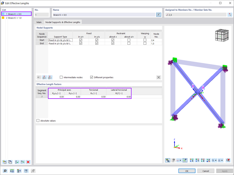
The second option is to physically divide the members into two parts and connect the four members with a standard node at the intersection (Image 3). Adding a Node on Member does not work, since it can only be associated with one of the X-brace members.
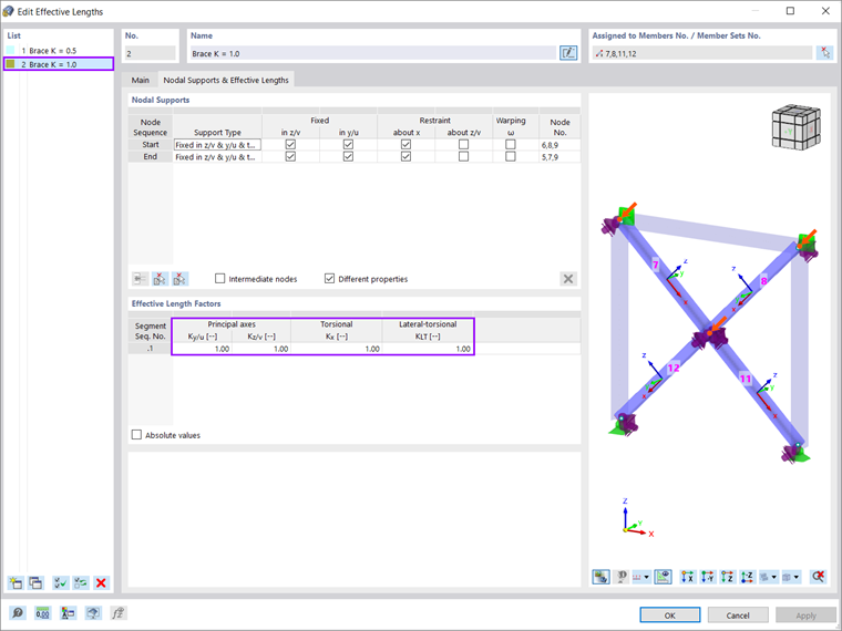
The overall results and design check ratios are comparable between the two approaches. The deflected shapes shown below look slightly different and the actual deflected shape may fall somewhere in between. The first option may be preferred to keep the overall number of members down and to prevent load-sharing between the connected braces.