


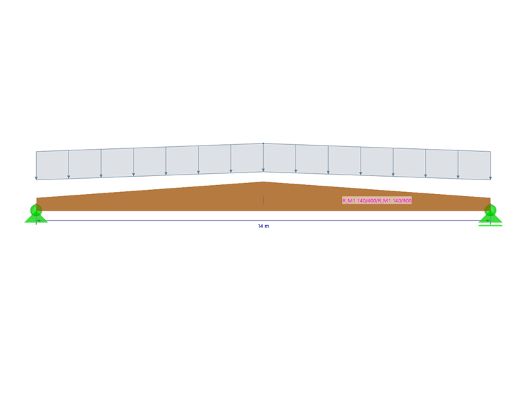
This article demonstrates how to use the equivalent member method for a tapered roof girder shown in Image 1.
Defining Modeling and Design Parameters in RFEM 6
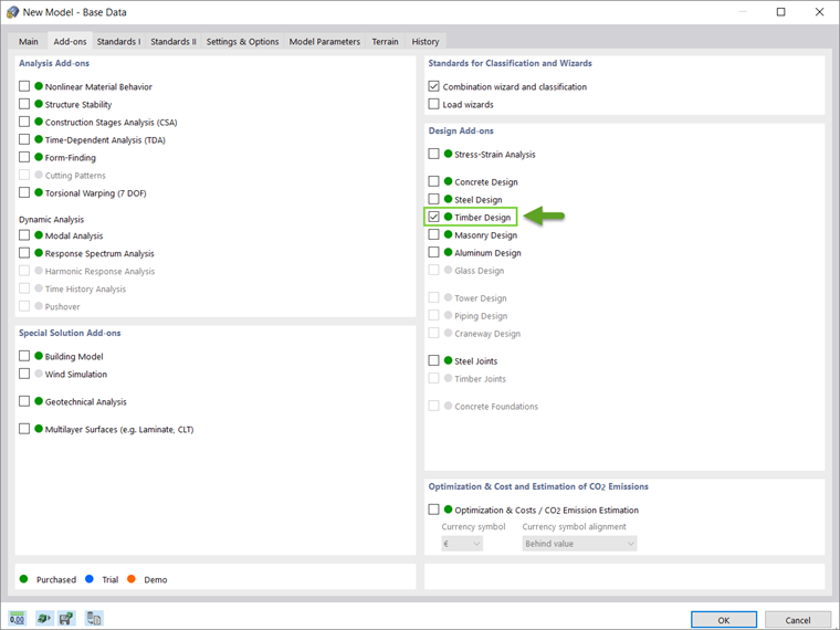
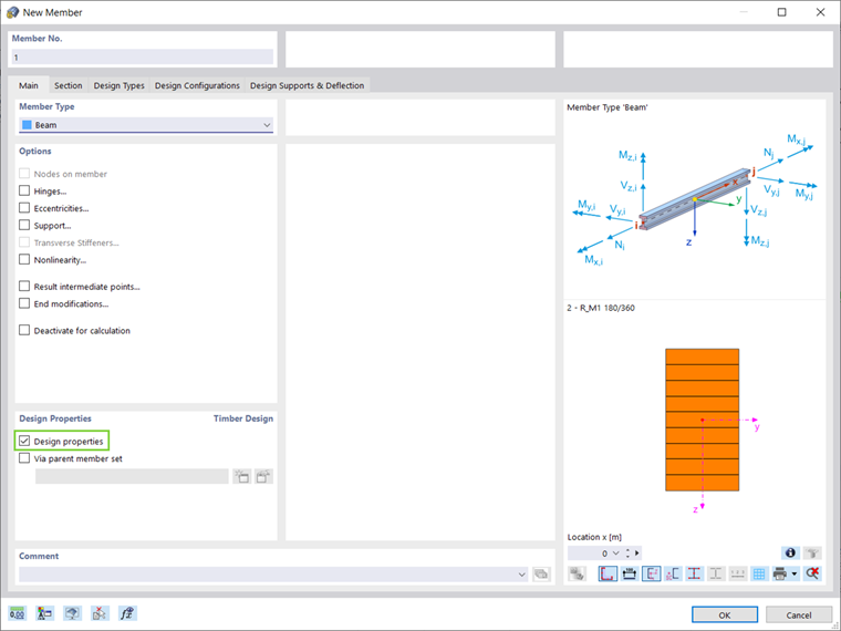
The stability design of timber structures according to the equivalent member method requires the activation of the Timber Design Add-on in RFEM 6 (Image 2). The add-ons are integrated in the RFEM environment so all design settings and parameters can be defined in parallel to the modeling. For this purpose, it is important to check the Design Properties box when defining the member (Image 3).
As Image 1 shows, the timber girder has a span length of 14 m and section dimensions of 140 x 400 mm and 140 x 900 mm at the end and middle of the span, respectively. The material used is glued-laminated timber GL28C and can be selected from the material library in RFEM 6. In addition to the member's self-weight, the girder includes a 1.75 kN/m permanent load and 3.4 kN/m snow load.
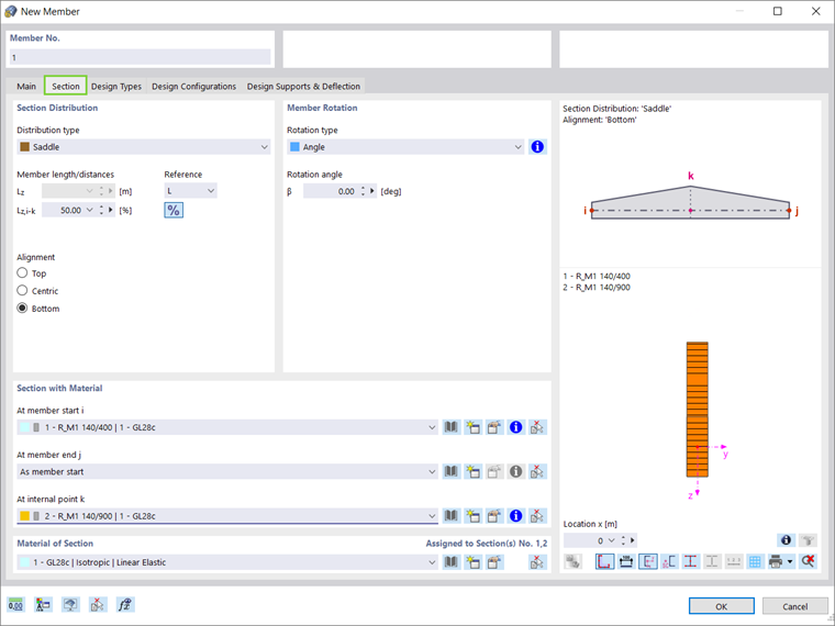
In RFEM 6, the section properties of the new member can be defined in the Section tab shown in Image 4. This roof girder type requires the selection of Saddle under the distribution type and an alignment with respect to the bottom of the section.
The distance k at which the section properties differ from those at the member start and member end can be set, and the cross-sections at these points can be assigned.
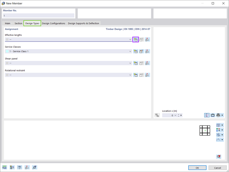
As mentioned before, RFEM 6 allows simultaneous definition of the modeling and design parameters. Therefore, the member properties including effective lengths, service classes, shear panels, and rotational restraints can easily be set in the Design Types tab of the New Member window. As Image 5 shows, no shear panel or rotational restraint is defined in this example, and the focus is set on the assignment of the effective length.
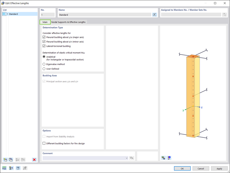
The definition of effective lengths is shown in Image 6. In general, the effective lengths can be considered for lateral-torsional buckling as well as flexural buckling about the major and minor axes. When designing according to the equivalent member method, the calculation of the elastic critical moment is analytical.
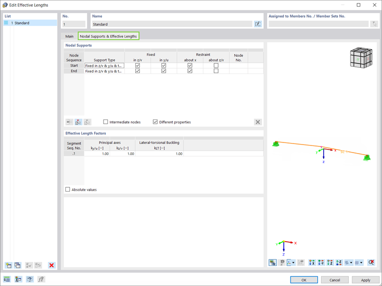
Next, it is possible to define the nodal supports and assign the effective length factors. In this example, nodal supports are assigned at the start and end of the member (Image 7), which will consider the entire member length for the stability analysis.
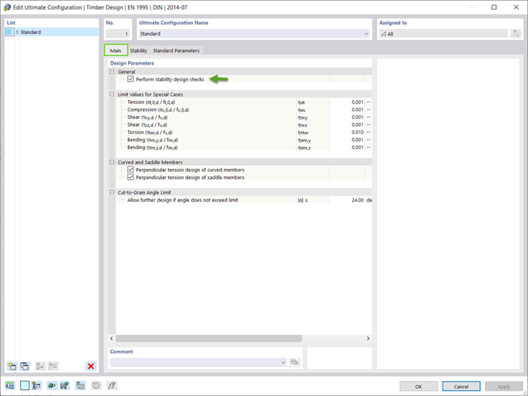
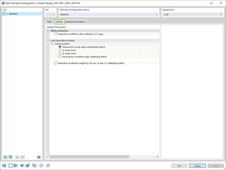
Before starting the calculation, the user can define the parameters for the Ultimate Configuration. The stability design checks can be activated in the design parameters of the Ultimate Configuration window (Image 8). At this point, the (de)stabilizing effect of the load that results in increasing the effective length can also be considered (Image 9).
Results
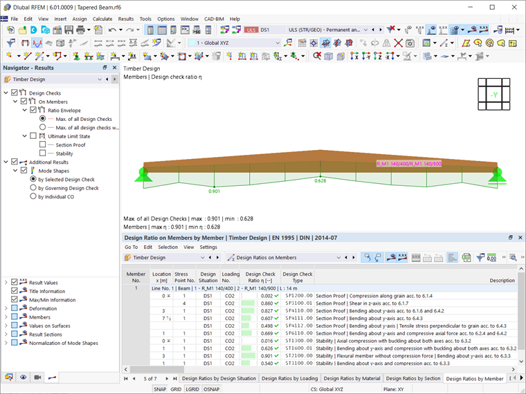
Once the calculation is done, the Timber Design results are available in both graphical and tabular form. As Image 10 shows, the design check ratios for each design type are displayed in the Results table, whereas all design check details can be accessed via the Design Check Details icon.
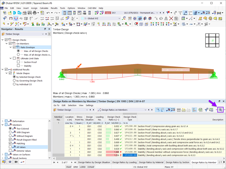
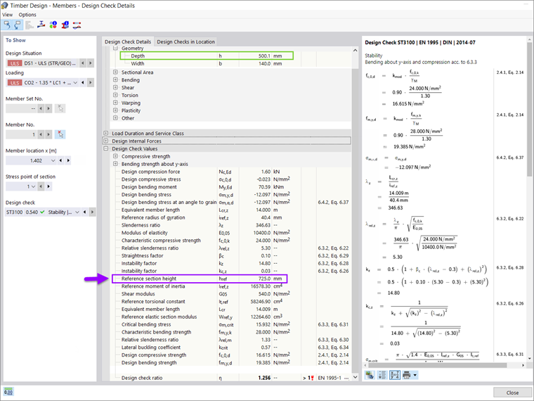
The possibility to perform stability design of tapered members in RFEM 6 based on the equivalent cross-section height is clearly displayed in the design check details. For instance, if the design check details for the stability design check type ST3100 (bending about the y-axis and compression according to 6.3.3., EN 1995 | DIN | 2014-07) are displayed, the depth of the section at the member location x=1.402 m is 500.1 mm (Image 11).
However, the depth value used to calculate the section properties (for example, elastic section modulus, moment of inertia, torsional constant, and so on) considered in the design check equations is in fact the Reference Section Height.
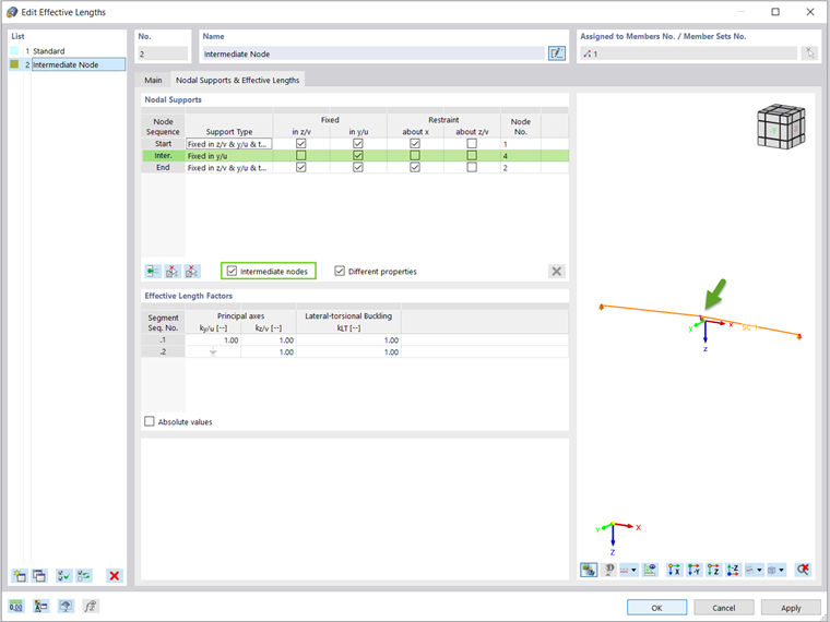
The results show that the full member length for the stability design leads to design ratios higher than 1. To overcome this issue, the effective length can be modified by defining restraints at the intermediate nodes along the span (Image 12). This new effective length results in improved design ratios, as shown in Image 13.
Final Remarks
Members with tapered cross-sections can be modeled in RFEM 6 in a simple and straightforward manner. The integration of the Timber Design add-on in the RFEM environment allows simultaneous definition of both the modeling and design parameters of these elements. In terms of stability analysis, one of the major advantages of RFEM 6 is the possibility to perform stability design of members with tapered cross-sections according to the equivalent member method.
In the fifth generation of the RFEM software, the design of tapered members according to the equivalent member method was not possible. Instead, the design of tapered members according to the equivalent member method was previously offered only in the RX-TIMBER stand-alone program.
It is important to mention that in addition to the equivalent member method, a stability analysis based on the eigenvalue method is also possible in RFEM 6. The stability analysis based on this method will be considered in an upcoming Knowledge Base article.