The member requirements are covered in a separate article, KB | AISC 341-16 Moment Frame Member Design in RFEM 6 .
More in-depth details on the Seismic Configuration input are covered in article KB | AISC 341 Seismic Design in RFEM 6 .
Connection Requirements
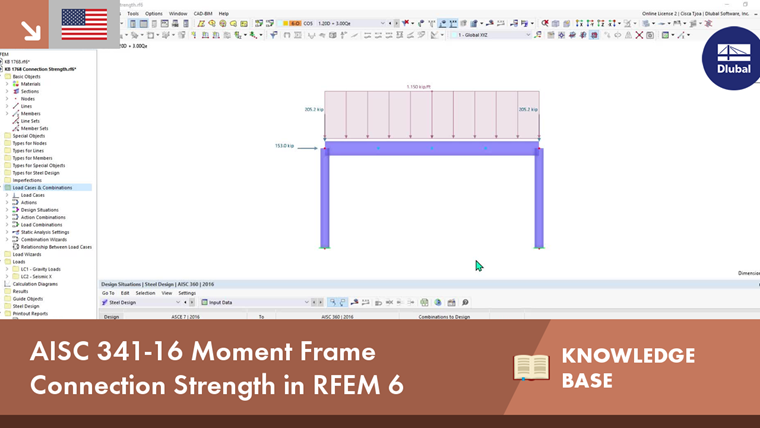
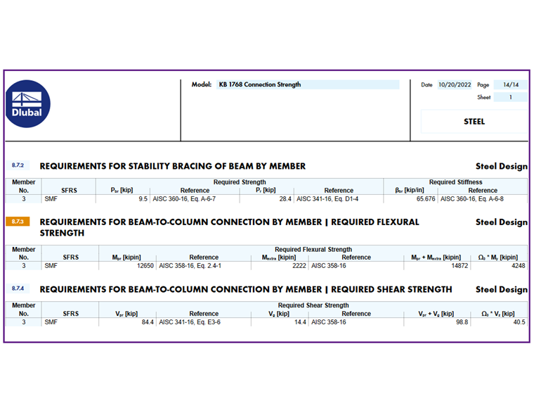
The "Seismic Requirements" include the Required Flexural Strength and the Required Shear Strength of the beam-to-column connection. They are listed in the Moment Frame Connection by Member tab. The design check details are not available for the connection strength. However, the equations and standard references are listed. The symbols and definitions are summarized in the table below (Image 1).
AISC Seismic Design Manual – Example 4.3.7 SMF Bolted Flange Plate (BFP) Connection Design
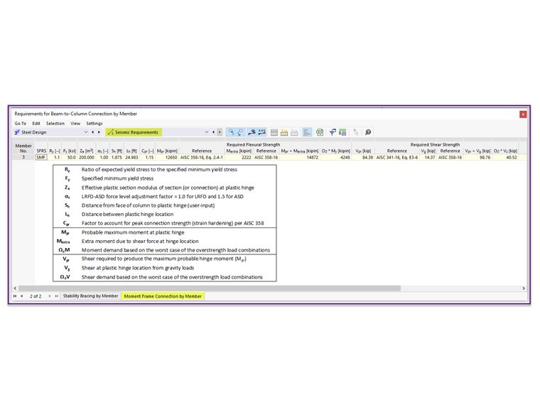
For simplicity, the RFEM model consists only of a single frame instead of the entire building that is presented in the AISC example (Image 2). The gravity load on the beam = 1.15 kip/ft.
The numbering of the steps in this example follows the step-by-step design procedure outlined in AISC 358-16 Section 7.6 [3].
Step 1. Compute probable maximum moment at the plastic hinge location, Mpr
|
Mpr |
Probable maximum moment at the plastic hinge |
|
Cpr |
Factor to account for peak connection strength (strain hardening) per AISC 358. Cpr = (Fy+Fu)/(2Fy) ≤ 1.2 |
|
Ry |
Ratio of expected yield stress to the specified minimum yield stress |
|
Fy |
Specified minimum yield stress |
|
Ze |
Effective plastic section modulus of section at the plastic hinge |
Steps 2 to 5 contain the bolt requirements and are outside the scope of the Steel Design add-on.
Step 6. Compute shear forces at the beam plastic hinge location, Vpr + Vg
|
Vpr |
Shear required to produce the maximum probable moment at the plastic hinge, Vpr = 2Mpr/Lh |
|
Vg |
Shear from gravity loads at the plastic hinge location, Vg = wuLh/2 |
|
Mpr |
Probable maximum moment at the plastic hinge location |
|
Lh |
Distance between plastic hinge locations |
|
wu |
Gravity loads on the beam |
Step 7. Determine moment expected at the face of the column flange, Mf
|
Mf |
Moment expected at the face of the column |
|
Mpr |
Probable maximum moment at the plastic hinge location |
|
Mextra |
Extra moment from the shear force at the plastic hinge location |
|
Vpr + Vg |
Shear forces at the plastic hinge location |
|
Sh |
Distance from the face of column to the plastic hinge location |
The above equation neglects the gravity load on the small portion of the beam between the plastic hinge and the face of the column (1.15 kip/ft*1.875 ft = 2.16 kips*22.5 in = 48.6 k-in). This value is permitted to be included [3].
Step 14. Determine the required shear strength at the face of the column, Vu
The required shear strength at the face of the column is used to design the beam web-to-column (single-plate) shear connection.
|
Vu |
Required shear strength at the face of the column |
|
Vpr |
Shear required to produce the maximum probable moment at the plastic hinge location |
|
Vg (at face of column) |
Shear from gravity loads at the face of the column |
|
wu |
Gravity loads on the beam |
|
Lcf |
Clear length of the beam, Lcf = Lbeam - dc = 360.0 in - 15.2 in = 344.8 in |
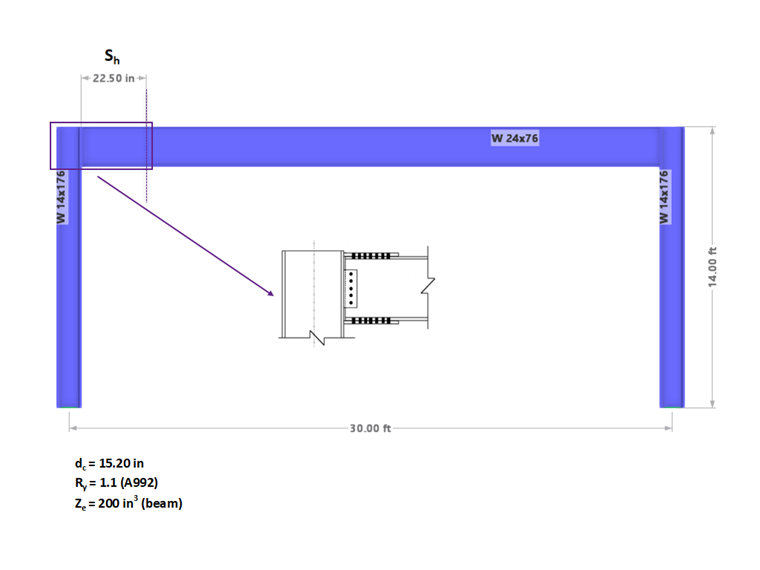
To be more precise, the calculation above shows Vg taken at the face of the column instead of at the centerline (as shown in the AISC example [2]). The small difference can be seen in the shear diagrams (Image 3).
The values obtained from the formulas above can be compared to the result produced by RFEM under the “Seismic Requirements” (Image 1). Small discrepancies are due to rounding. The result can also be included in the printout report (Image 4).
The detailed procedures to design bolts, flange plates, single-plate, continuity plates, and doubler plates are not part of the scope. Therefore, the steps for these checks were omitted in this article.
The moment and shear demand based on the worst-case scenario of the overstrength load combinations, ΩoM and ΩoV are also listed. For the design of ordinary moment frames (OMF), the potentially limiting aspects of the connection strength include the overstrength seismic load [AISC Seismic Design Manual Section 4.2(b)].