More in-depth details on the Seismic Configuration input are covered in a separate article, KB | AISC 341 Seismic Design in RFEM 6 .
Member Requirements
The following design checks for members that are part of the seismic force-resisting system (SFRS) are available in RFEM. The sections listed refer to Seismic Provisions AISC 341-16 [1].
- Width-to-Thickness Limitations [Section D1.1]
- Stability Bracing of Beams - Required Strength & Stiffness [Section D1.2a.1(b) for IMF and D1.2b for SMF]
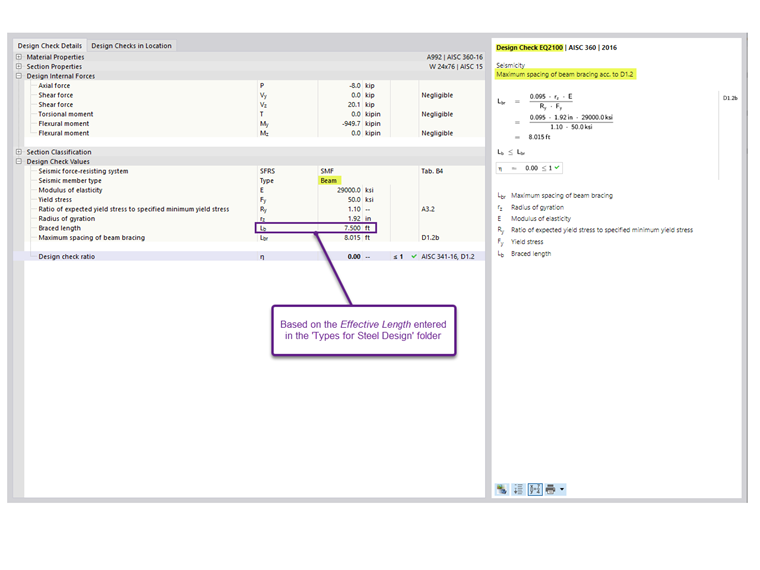
- Stability Bracing of Beams - Maximum Spacing [Section D1.2a.1(c) for IMF and D1.2b for SMF]
- Stability Bracing of Beams at Hinge Locations - Required Strength [Section D1.2c.1(b)]
- Column Required Strength [Section D1.4a]
- Column Slenderness Ratio for Unbraced Connection [Section E3.4c.2b]
Width-to-Thickness Limitations for Ductility Requirements
Members in IMF are designated as moderately ductile members according to Section E2.5a. Members in SMF are designated as highly ductile members according to Section E3.5a.
Column Flange
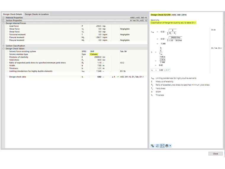
The column flange of SMF must satisfy the requirements of AISC Seismic Provisions Section D1.1 [1] for highly ductile members. This design check is shown as EQ 1200 in RFEM (Image 1).
Column Web
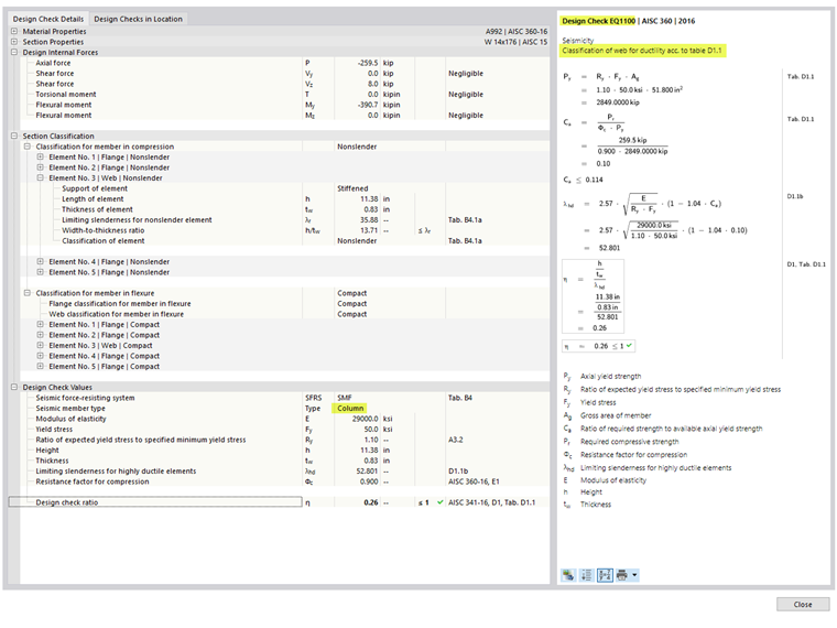
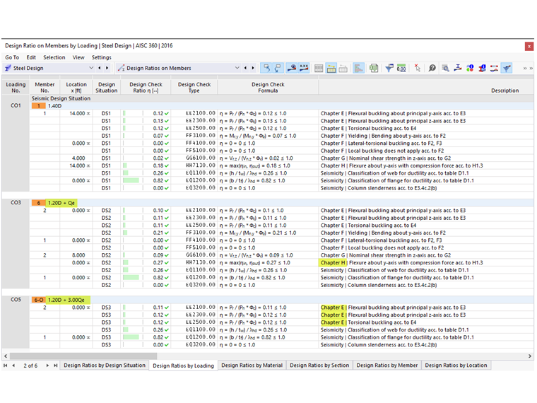
The limiting width-to-thickness ratio for webs of highly ductile members is determined using the governing load case for axial load, as stipulated in Section D1.4a [1]. The governing load case is based on all load combinations, including gravity only CO, CO with standard seismic load, and CO with overstrength seismic load. This check is shown in EQ 1100 in RFEM (Image 2).
Similar to the columns, the width-to-thickness checks are also done for the beams.
Stability Bracing of Beams
The required strength and stiffness of the stability bracings are listed in the Stability Bracing by Member tab under “Seismic Requirements” (Image 3). These values can be compared to the calculated available strength and stiffness when designing the bracing members that frame into the beam. There are no design check details available (only references).
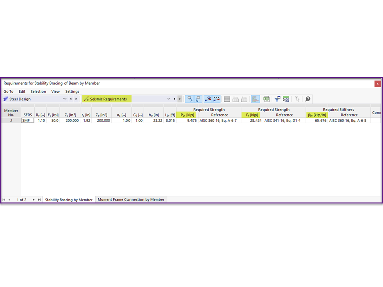
There are two different values listed for the required strengths. The first value, Pbr, is applicable for the stability bracings that are located outside the plastic hinge location. Pbr is defined in Equation A-6-7 of Appendix 6 of AISC 360-16 [3]:
|
Pbr |
Required strength of the stability beam bracing |
|
Mr |
Required flexural strength of the beam. Mr = RyFyZ/αs [AISC 341 Equation D1-1] |
|
Cd |
Double curvature factor = 1.0 [AISC 341 Section D1.2a(b)] |
|
ho |
Distance between the flange centroid ho = d - tf |
The second, larger value, Pr, is specifically for the stability bracings at the plastic hinge location. It is defined in Equation D1-4 of AISC 341-16 [1]:
|
Pr |
Required strength of the stability beam bracing at the plastic hinge location |
|
Ry |
Ratio of the expected yield stress to the specified minimum yield stress |
|
Fy |
Specified minimum yield stress |
|
Z |
Effective plastic section modulus of a section (or a connection) at the plastic hinge location |
|
αs |
LRFD-ASD force level adjustment factor = 1.0 for LRFD and 1.5 for ASD |
|
ho |
Distance between the flange centroid |
The required stiffness, βbr, is defined in Equation A-6-8 of Appendix 6:
|
βbr |
Required stiffness of the stability beam bracing |
|
Mr |
Required flexural strength of the beam |
|
Cd |
Double curvature factor = 1.0 |
|
Lbr |
Maximum spacing of the stability beam bracing |
|
ho |
Distance between the flange centroid |
The maximum spacing of the stability bracing must satisfy the requirements of AISC 341-16 Section D1.2a.1(c) for IMF and Section D1.2b for SMF.
|
Lbr |
Maximum spacing of the stability beam bracing |
|
ry |
Radius of gyration about the weak axis |
|
E |
Modulus of elasticity |
|
Ry |
Ratio of the expected yield stress to the specified minimum yield stress |
|
Fy |
Specified minimum yield stress |
The design check for the maximum spacing is presented together with the other member requirements under “Design Ratios of Members”. The design check detail is shown in EQ 2100 (Image 4). The braced length, Lb, is the specified effective length for lateral-torsional buckling (LTB).
Column Required Strength
All columns that are part of the seismic force-resisting system (SFRS) are required to be designed with the overstrength loads. In many cases, the amplified axial force does not need to be combined with the concurrent bending moments. The option to neglect all bending moments, shear, and torsion in columns for overstrength limit state is activated by default. This option can be deactivated in the Seismic Configuration.
For standard load combinations without overstrength from seismic load effect, the combined loading is checked according to AISC 360-16, Chapter H.
For load combinations with overstrength seismic load, Chapters F and H are not checked when the option to neglect all bending moments, shear, and torsion in columns for overstrength limit state is activated.
In Example 4.3.2 of the seismic manual [2], the controlling case from both load combinations, standard and overstrength, needs to be considered.
Bending moments resulting from a load applied between points of lateral support can contribute to column buckling. Therefore, they are required to be considered concurrently with the axial loads by deactivating the option to neglect the moments.
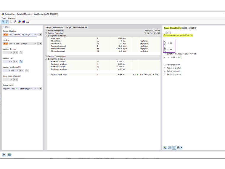
Column Slenderness Ratio for Unbraced Connection
For columns in SMF with no transverse member bracing at the connection, the potential for out-of-plane buckling at the connection shall be minimized by limiting the slenderness ratio L/r to be equal to or less than 60, according to Section E3.4c.2b [1]. Unbraced connections occur in special cases, such as in a two-story frame without an intermediate floor.
In all other cases, the option to meet this requirement can be deactivated in the Seismic Configuration.
The connection requirements are covered in the article KB | AISC 341-16 Moment Frame Connection Strength in RFEM 6 .