In RSECTION, you can import cross-section geometries that are available as contour or centroid layouts in DXF format and use them as a basis for modeling.
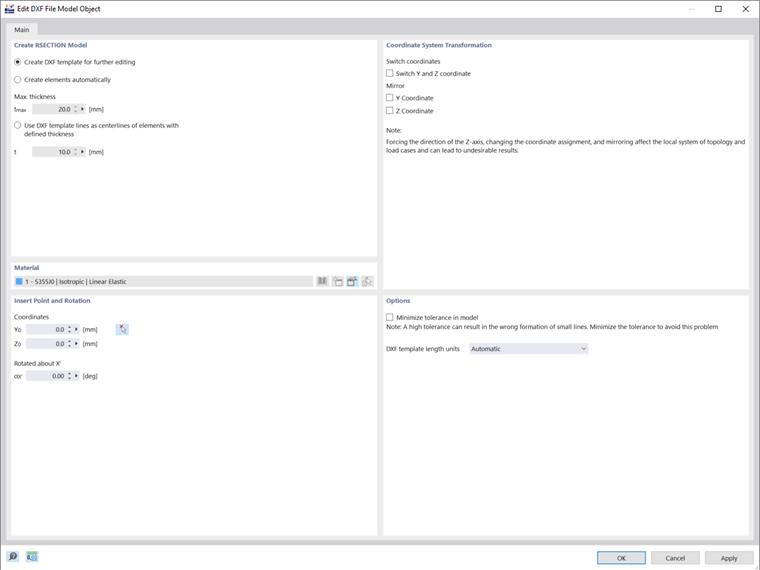
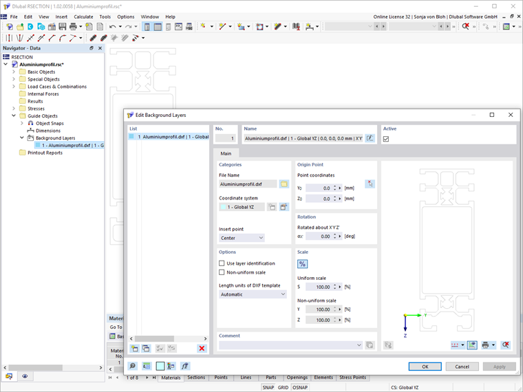
Start the import in the File menu under Import → DXF. After selecting the DXF file to be imported, it is necessary to specify further settings in the import dialog box (Image 01).
You can manually enter the insert point or define it graphically in the work window by using the
![]() button. The DXF template can also be rotated. A positive angle α rotates the template clockwise.
button. The DXF template can also be rotated. A positive angle α rotates the template clockwise.
It is also possible to transform the coordinates. You can swap the Y- and Z-coordinates, but you can also mirror them.
There are three options for creating the cross-section:
- Creating a DXF template for further editing
- Creating Elements Automatically
- Considering lines of a DXF template as center lines of elements with assigned thickness
The last two functions will generate elements, including related parts. In the list of already created materials, you can select a material, edit it, or define a new one.
Creating a DXF template for further editing
The lines in the DXF file are imported as lines so that you can use them as an aid for further modeling.
This function is useful for massive cross-sections for which only parts but no elements have to be created.
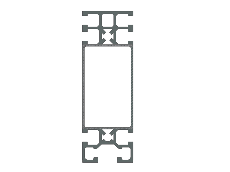
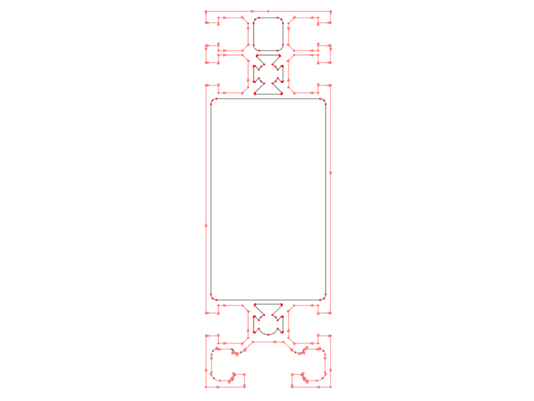
Furthermore, the function can also be used for complex cross-sections for which you want to create only elements for the governing cross-section parts. Image 02 shows a cross-section where only the webs are prone to buckling. You only need to create elements for the webs and flanges. The elements of the flanges are necessary for the correct support of the subpanels. Please note that the stresses at the effective cross-section are only calculated at the defined elements.
Creating Elements Automatically
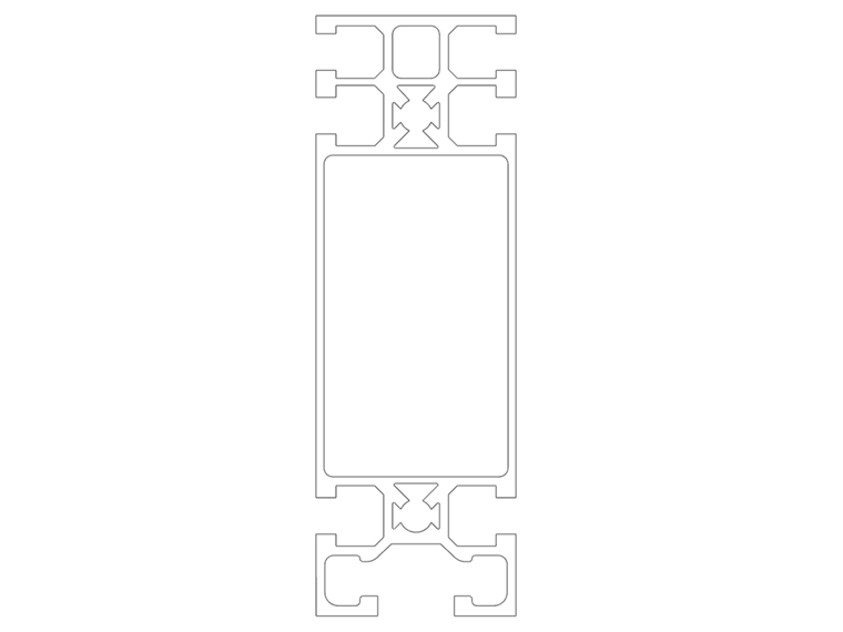
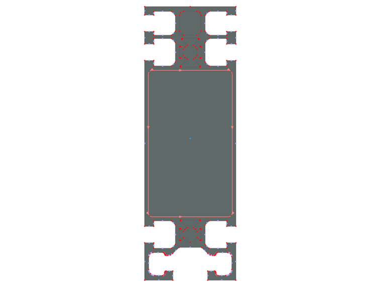
We recommend automatically creating elements if the contour lines of the cross-section are available in a DXF file (Image 03). RSECTION determines the center lines between parallel lines, then it creates the elements including related parts between the intersections. Only elements are generated that do not exceed the maximum thickness defined in the "Max. thickness" field.
Considering lines of a DXF template as center lines of elements with assigned thickness
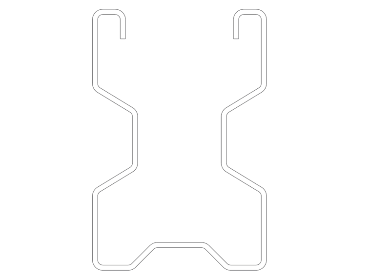
If the cross-section geometry is available as a center line model (Image 04), you can consider the lines of the DXF template as the center lines of the elements. The thickness defined in the "t" field is assigned to all elements.
Background Layer
You can use a DXF file as a background layer (Image 05) for entering objects. To insert a background layer, use the Guide Objects → Background Layers item on the Insert menu.
In contrast to the DXF import, where a new file is created, the background layer is inserted into the current file.
When importing the file as a background layer, no points and lines are generated; instead, the background layer serves as a snap grid to help in further modeling.
Editing with Modeling Tools
Using the modeling tools, you can post-process the generated objects and add missing objects.
To enter a part, you can use the "Select Boundary" function. RSECTION recognizes the part automatically as soon as a sufficient number of boundary lines is defined (Image 06).
In the same way, you can define openings using the "Select Boundary" function (Image 07).
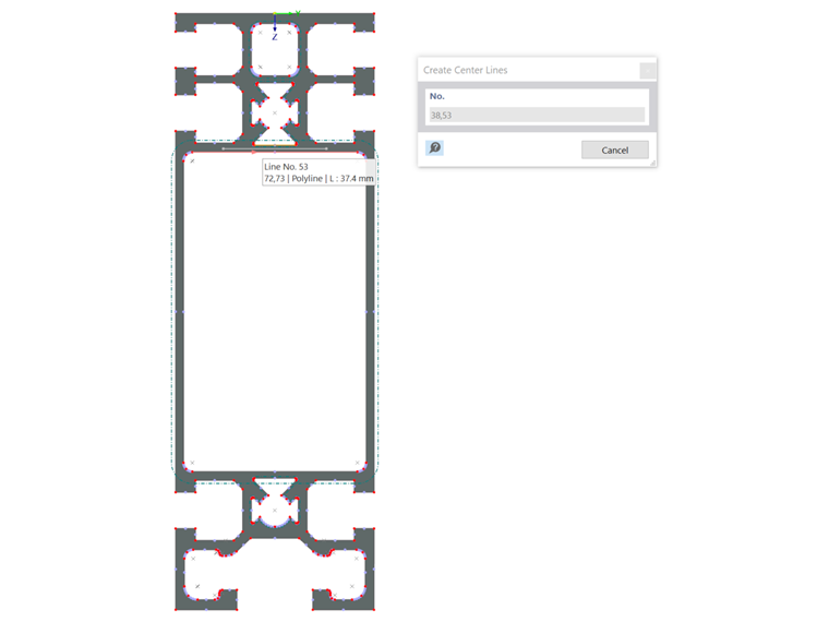
Using the "Set Center Lines" and "Set Center Lines | Angle Axis" functions on the Tools menu, you can create center lines between two lines. To create the lines, click both lines one after the other (Image 08).
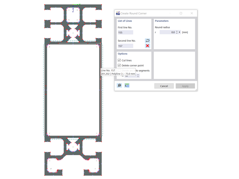
If there is no intersection point between the center lines, you can extend the center lines. On the Tools menu, you can use the "Extend or Trim Lines", or "Create Angled Corner", or "Create Round Corner" functions (Image 09).
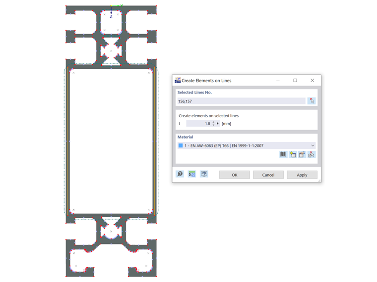
Then, you can set the elements at the center lines using the "Create Elements on Lines" function. Specify the actual element thickness and select the lines (Image 10).
Cross-section modeling based on DXF files is shown in the video, which you can find in the top left corner of this article.