130 Results
View Results:
Sort by:
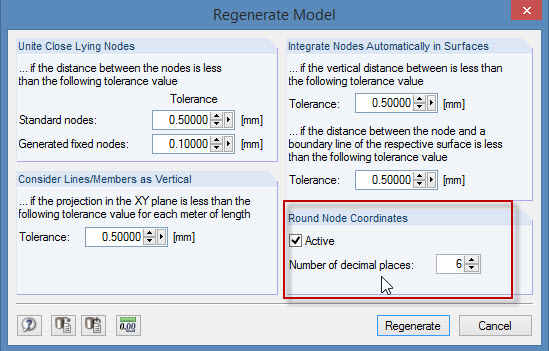
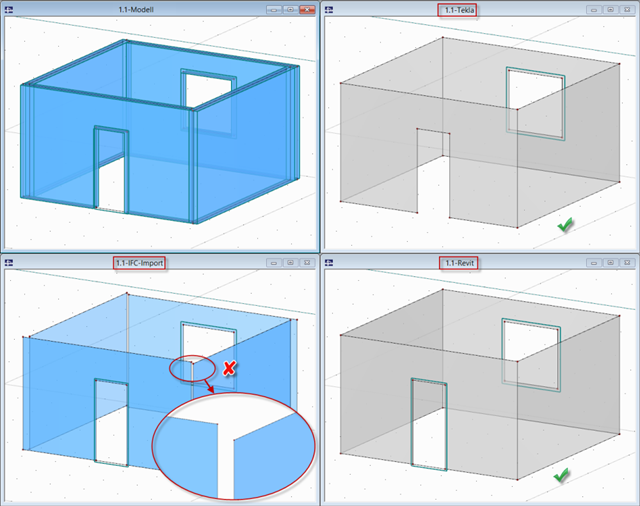
During the cooperation between the structural and design engineers, the DXF format is often used if there is no direct interface. However, the geometrical data of these DXF files are not always accurate. For example, an inaccuracy in the third decimal place is not noticeable, but it can lead to numerical problems when generating the FE mesh in RFEM.
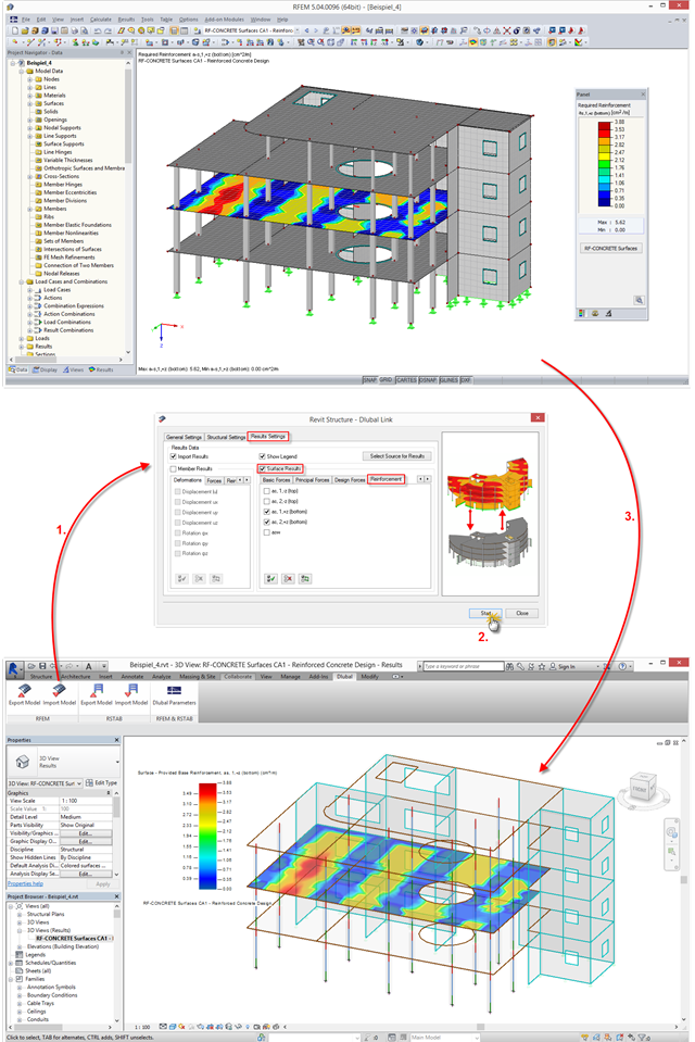
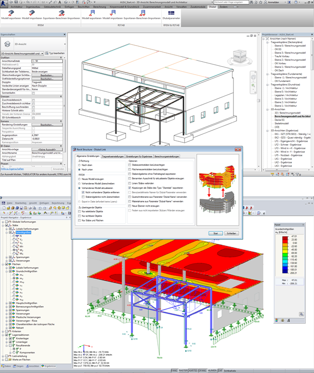
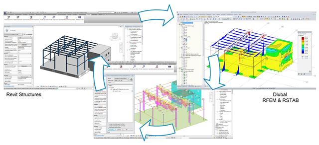
The interface between RFEM/RSTAB and Autodesk Revit has been improved: You can now transfer results from RFEM/RSTAB to Revit and display them there graphically. This option is available in a new tab when importing a file.
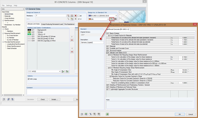
In order to meet the requirements for the parameters of special buildings modified according to standard adjustments, you can create new National Annexes from an existing one. To do this, copy the National Annex and adjust the parameters to the requirements.

Plan changes, even at an advanced stage of planning, or modifications of existing buildings are part of the daily routine of many structural engineers.
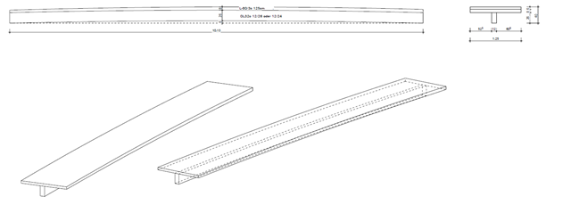
Our client had the exciting task of modeling a cross‑laminated timber plate with a precamber such that, in the case of a span of more than ten meters, the deformation was below the limit value of l/300 = 3.3 cm. The idea was to screw the plate on a glulam beam and then put it together with a glue approved by the building authorities in order to create a rigid bond between the plate and the member.
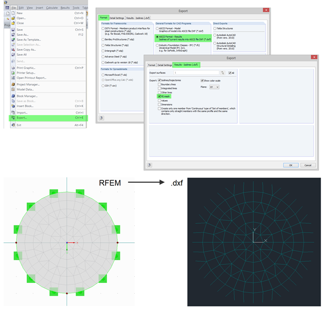
In RFEM, you can use the export function to export the generated FE mesh in DXF as a result. To do this, open the export dialog box in the program and select "ASCII Format - Results". In addition to a result (for example, isolines), you can select the FE Mesh in the "Results - Isolines (.dxf)" tab. After the export, the mesh in DXF is available in the DL‑FE‑MESH layer.
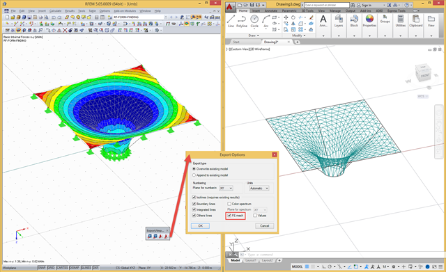
In RFEM, there are a file‑based and a direct DXF interface. The file-based DXF interface allows you to export the data in a DXF file that is transferred directly into an open AutoCAD file. In the interface dialog box, you can select which data are to be exported (results as isolines, result values, or finite element mesh with boundary and integration lines).
The increasing use of the BIM method in planning buildings also opens up new possibilities for structural engineers. Once a comprehensive 3D model of a building has been created, you want to continue using it for the structural analysis and gain the maximum benefit from it. However, there are also some new challenges for the structural engineer and the software used, which are described in this article.
Modern buildings are designed with spaces tailored to personal desires and dreams, expressing individual lifestyles. These requirements often include ceilings - whether in houses, office buildings, or public buildings - that have an enormous span and no support, allowing optimal use of the space below. However, this requires a very high stability level for load‑bearing capacity and serviceability reasons. By extending the size of beam or plate cross-sections, you can increase the stability, but the cost effectiveness decreases because of the additional consumption of material. One common solution for these large spans is to use timber or steel downstand beams.

RFEM and RSTAB provide numerous interfaces with other programs for data exchange. In the respective programs, different names are often used for the same materials and cross-sections. Therefore, it is necessary to convert the material and cross‑section names in order for them to be recognized by the program after the data exchange.
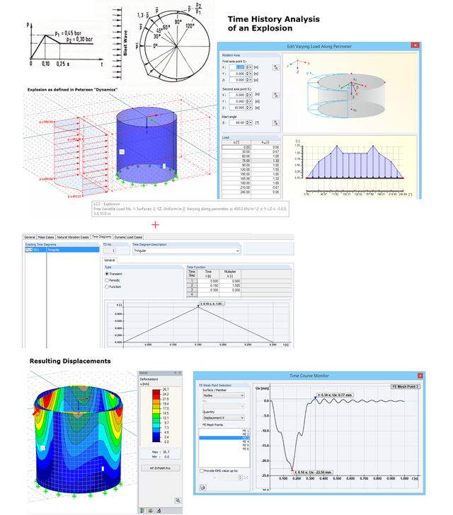
With RF-DYNAM Pro – Forced Vibrations, you can perform a time history analysis. For example, you can analyze an explosion acting on a nearby building structure. In "Dynamik der Baukonstruktionen" by Christian Petersen, formulas for time diagrams and load distribution are described to specify an explosion. The image shows the input of such an explosion load. Free variable loads are available in RFEM that enable flexible load distributions.
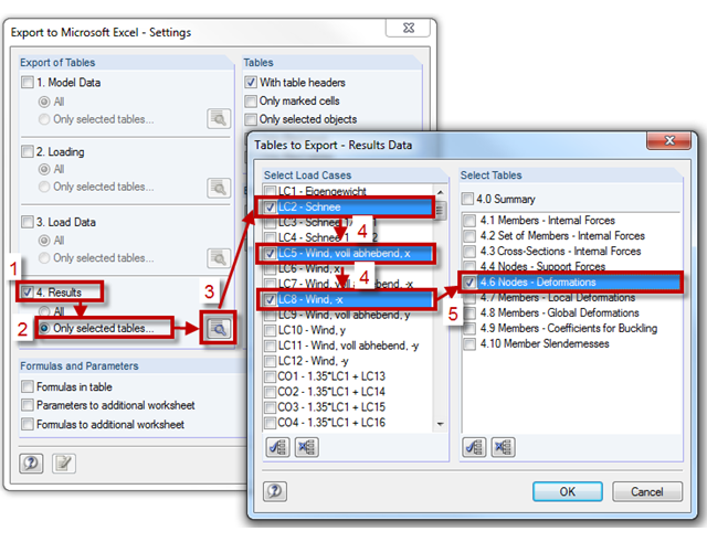
RFEM and RSTAB provide the export interface ("File" → "Export") to export model and load data, as well as results, to Excel or in a CSV file in one step. You can select the tables to be exported in the "Export Tables" section. The "Only selected tables" option allows you to export only a specific selection of tables. Use the [Select Load Cases and Tables for Export] button to open the corresponding dialog box.
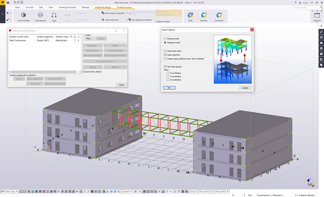
In RFEM and RSTAB, several interfaces are available. The DSTV interface (*.stp) is the most convenient for importing beam structures, since supports, hinges, loads, and load combinations are also transferred, in addition to the general topology.
A successful project process involves not only the building owner and the engineer, but also the designers. These days, they also have to design standard connections in steel structures themselves. To do this, the corresponding internal forces of connections are required.
In his bachelor's thesis, Jonas Mösch analyzes the open and closed interfaces in BIM-based structural design. The theoretical section covers the definition of the term "Building Information Modeling".
The Master's Thesis of Tamás Drávai, Haroon Khalyar, and Gábor Nagy deals with the effect of interoperability between Computer Aided Design (CAD) and Finite Element Modeling (FEM) software on structural modeling and analysis. Several case studies were conducted, where a building information model was transferred from CAD to FEM software with different data exchange formats.
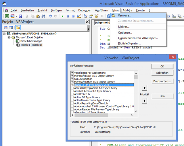
The first part of the post about the COM interface describes opening and closing RFEM. VBA programming language is used in Excel; however, the program sequence is the same as for programming with C#. First, it is necessary to add the corresponding reference in VBA to recognize the commands for the interface. The image on the left shows an example of RFEM 5.
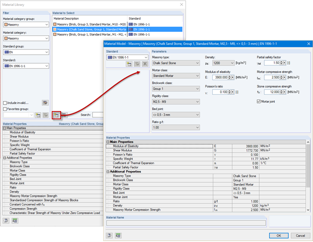
In order to estimate the structural behavior of masonry close to reality by using RFEM, it is necessary to select a material and a material model first. Since masonry responds to tension by cracking, you have to select a nonlinear material model. This can be selected if the RF-MAT NL add-on module is available.
The first part of the article series about the COM interface described opening and creating a model in RFEM. The second part explains creating and modifying elements on an example of a member. The elements described in Part 1 will not be explained again here.
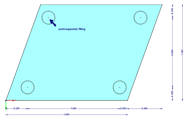
The transparency of the glass material should not be missing in any building. In addition to the typical application areas such as windows, this building material is increasingly being used for facades, canopies, or even as bracing of stairways. Of course, the planning architects often set a very high standard of transparency on fixation of the glass panes. This requires special glass fittings that couple the glass panes.