


Elimination of non-structural components
One of the main advantages of 3D-BIM models is that all information is available centrally in a database. If it is assumed that a building design is initially created by the architect, the focus is not primarily on the structural system. The focus of his/her work is primarily on the use and design of the building, as well as adherence to a cost frame in close cooperation with the building owner. Based on this fact, required supporting structures are designed for the building. This structural model represents the load-bearing framework of a building, so to speak, and is of particular interest to the structural engineer. The remaining non-load-bearing parts of the building are either insignificant for him/her (for example, detailed designs of doors and windows, precise floor structure, electrical installation and plumbing, and so on), or are, at most, important for load assumptions. Therefore, only a part of the BIM model has to be evaluated by the structural engineer, and he/she has to separate structurally relevant objects from irrelevant ones. However, the information as to whether or not a structural component available in the BIM model contributes to the analysis of the structural system is not necessarily included in every BIM model and must either be given to the model by the structural engineer, or he/she must remove those elements that are not essential to him/her using the corresponding filters. BIM software that allows you to mark components as load-bearing in the architectural model is available on the market. Provided that the architect considers it his/her task to carry out this marking, an automated model transfer to the structural analysis software is facilitated.Physical structural model and idealized analysis model
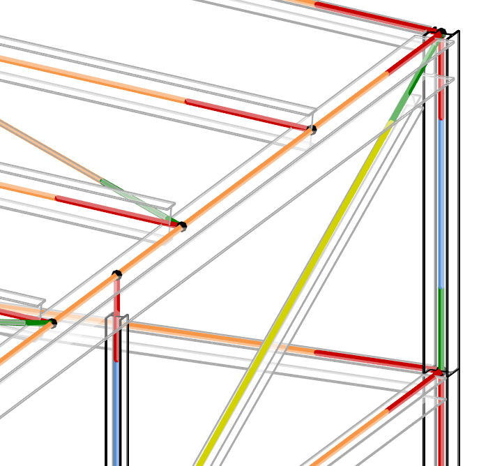
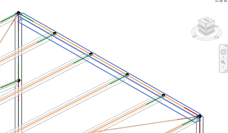
Once the load-bearing structural components have been eliminated from the global BIM model, the physical structural model is available, which corresponds in position and shape to the later real (solid) model. Due to limited computational capacities and necessary simplifications for the calculations, however, not all structural components are usually calculated as solid models, but are reduced to member and surface elements, to the results of which (for example, internal forces for member and surface) the current standards also refer. The use of solid models is usually limited to very thick structural components or to the analysis of special sub-areas (such as steel connections), which includes details like screws, welds, or contact conditions. The reduction to members and surfaces raises the issue of the position of the centroidal axes of these structural components and how they are connected to each other. Due to different component heights, cuts, and connections, no consistent center line models may be connected in one point, which must be further adjusted in order to serve as an analytical calculation model. This results in further questions for the structural engineer.- Where should the system lines be located?
- How do you deal with possible member and surface eccentricities?
- Do system lines have to be shortened or extended, and what is their influence on the loading (self-weight, line loads, surface loads, and so on)?
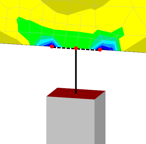
- Is it enough to model the structure by means of simple analytical nodes, or is it necessary to create extended models adjusted to civil engineering purposes (for example, a column connects to a ceiling only in one node: problem of singularities)?
- Are the connections of the members and surfaces hinged, semi-rigid, or rigid?
- Which locations should be considered as supports, and with which support conditions?
- Can members or surfaces be subdivided in order to gain a reasonable analysis model?
When making decisions for all these questions, software can usually provide little support, and these decisions have to be made finally by the structural engineer. A new trend in architecture and construction software, however, is the fact that structural systems are already carried within the programs and are also partly created automatically. The advantage is that once correctly defined, structural basic systems, ideally including loading, can then be transferred to a structural analysis program without major reworking.
However, a prerequisite for this is that this BIM software is operated by users who also have the appropriate knowledge of structural analysis and the application of calculation programs. Seen from a traditional point of view regarding the usual responsibilities of architectural offices and offices for structural analysis in Germany, this fact is often the reason that the data exchange, and thus the BIM workflow, stalls. After all, the architect is not paid to create the structural analysis model.
Special aspects of modeling
When creating finite element models, special auxiliary structures and workarounds may be required at transitions from surfaces to member elements or, for example, in downstand beams. These auxiliary constructions require manual reworking of imported structures. This inevitably leads to the initial BIM model and the idealized analysis model drifting further apart, and the assignment of related structural components in the user programs of different disciplines is considerably more difficult.
This problem is particularly reflected when adjusting any modifications in both models. Often, rigid coupling members are used for coupling permanently connected components in the structural model representation. However, depending on the implementation in the structural analysis software, these special member types can lead to numerical problems if they are very short and stiff. Therefore, special attention is needed when automatically creating such coupling elements coming from BIM software. One large and, sometimes, not easily recognizable problem may be structural components that are supposedly connected in an analysis model. Due to BIM software modeling inaccuracies, or to numerical accuracy restrictions, it is also possible that FEA nodes are created that lie very close to each other. These nodes either cause difficulties for generating the mesh or pretend to be connected structural components that are not connected in the calculation model. This results in incorrect calculation results. Therefore, special attention must be paid to checking the imported model.
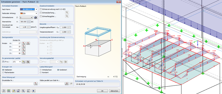
Load assumptions and load combinations
In some BIM applications, you can also specify loads and load combinations. The determination of, for example, wind load profiles, snow loads, or loads from earth pressure has become considerably more complex due to the Eurocodes introduced in recent years. The same applies to the rules for creating load combinations according to different design situations. Naturally, structural analysis programs are better suited for those tasks; they are more versatile and offer comprehensive generation tools. Therefore, it is obvious that load input and combinatorics are performed in the structural analysis application. If the resulting loads and combinations are transferred back to the BIM model, the parameters based on the automatic generation are usually lost, and thus the intelligence of the load objects is missing in case of further changes.
Considerations for calculating structural systems
If an adequate analysis model is derived from the BIM model, it can be calculated in the structural analysis software. It is necessary to decide which calculation theory and material models are used. After the calculation, the model may have to be adjusted, variants of the modeling are created, or new elements will be added or removed. Releases and supports must be checked. For designing the structural system, further assumptions and parameters have to be entered. Cross-sections and dimensions may change. The classic BIM concept would require that these specifications and assumptions are also stored in the central BIM model. However, this is not completely feasible currently; it is not supported with the usual interfaces or is only possible if the intelligence of the objects is lost.The consideration of construction stages sometimes plays a very important role for spatial models and determines the usefulness of the calculation results. Therefore, it is absolutely necessary to make sure before the calculation whether a calculation on the entire model requires the consideration of construction phases, or if partial models should be calculated in sections. In this context, it should be mentioned that BIM does not automatically mean that the entire building model is always calculated spatially. One good strategy is to detach the individual structural units successively from a BIM overall model and calculate them separately.
Changes in BIM model due to structural analysis
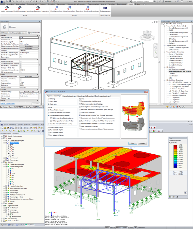
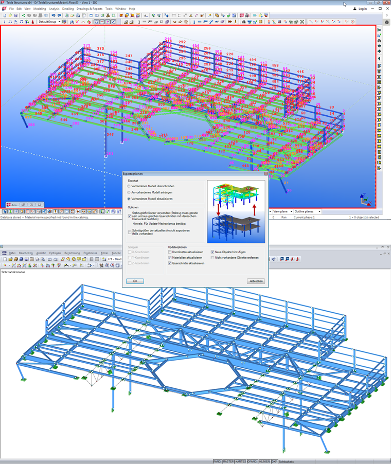
After the calculation is completed, material and cross-section changes may occur, or components such as bracings or downstand beams may be moved, removed, or added. These changes must be reflected and updated in the BIM model. But what happens if there are also changes in the original BIM model that have to be synchronized? How do you decide which is the last revision state? This process must be subject to certain rules, and the existing changes must be approved by responsible cooperators. Meanwhile, it must be ensured that changes in the BIM model are taken over after the import into the structural analysis software. Changes may occur on the same structural component at the same time in both the BIM and the analysis model. Such situations could be eased by blocking particular parts in the model or by the agreement of the involved parties. The automatic transfer of profile changes, surface thicknesses, or the addition and removal of new structural components in the respective other model is usually possible and is supported, for example, by Dlubal software. It should be noted that updates resulting from the structural analysis do not overwrite other information in the BIM model that is not relevant for the structural analysis.
IFC interface and direct coupling of software
For consistent planning, functioning interfaces are necessary. If you have open access to the data of the exchanging programs via programmable interfaces, they can be directly coupled without exchanging files. Both programs must be installed on the same computer. The implementation of such interfaces can be designed very flexibly and is not linked to the syntax and data models of general interface formats, as they are necessary for exchanging files. When exchanging data via neutral, manufacturer-independent file formats, the IFC format plays a major role.
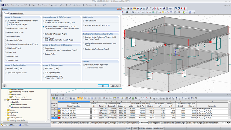
However, if a software is IFC-certified, this does not necessarily mean that the transfer to the structural analysis software is also possible. A certification is currently available only for the "Coordination View". It describes primarily the geometry of the structure on the basis of solid models; that is, the physical structural model mentioned above. For the structural model, the "Structural Analysis View" is provided, which also allows the transfer of supports, releases, and loads. For an IFC-based data exchange based on an architectural design program, it is, therefore, necessary to check which view can be exported.
Summary and conclusion
3D BIM models help the structural engineer to understand complex structural systems and to create analysis models faster with data transfer. Generally, the BIM model and the analysis model are different and geometrically not identical. Automatically generated analysis models must be checked carefully, and the calculation on the entire model may require the consideration of construction stages. The structural analysis may require special modeling at specific points and usually needs additional information that cannot, or can only partially, be stored in the BIM model. Due to possible modifications during the planning phase, it is necessary to define rules about who can make changes on the model, at which point of time, and exactly where. BIM and BIM software require broader and more comprehensive knowledge of all planning phases for architects and structural engineers, in addition to the willingness to rethink the traditional division of labor and to understand the planning task as teamwork. If you accept an initial, manageable additional effort, also considering subsequent planning steps, savings can be considerable and the planning results can be better. Planning offices that have dedicated themselves to the BIM process in recent years can confirm this. Not least because of this fact, but also because contracting authorities specify BIM as a planning method, BIM will continue to spread in years to come. Structural engineering is an integral and essential part of Building Information Modeling; therefore, BIM-capable structural analysis software and the handling of entire models will become more important.Dlubal Software focuses on the BIM-based planning process; it offers a variety of interface formats and direct connections to common BIM software products. With its open, programmable interface, the software can be integrated seamlessly into company-specific planning processes. This allows for automating modeling tasks and processing calculation results.