1098 Results
View Results:
Sort by:
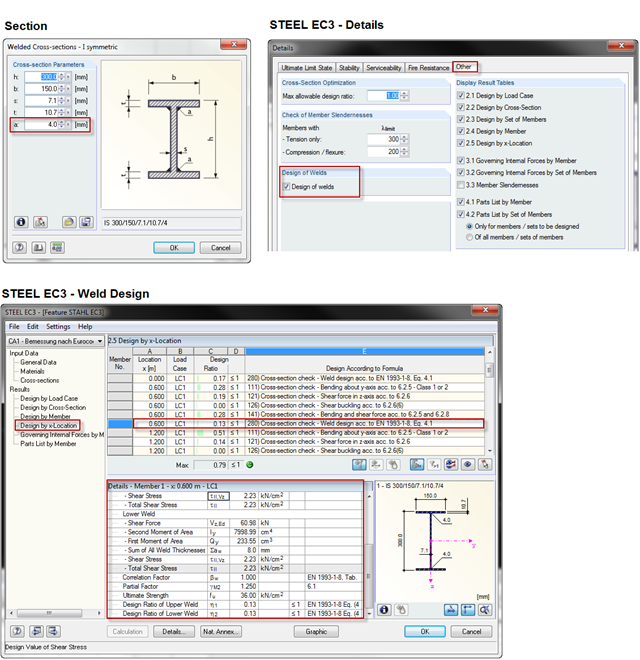
When using a welded profile, weld seam verification can also be carried out in RF-/STEEL EC3 as part of the design. The program performs the typical designs according to EN 1993‑1‑8.
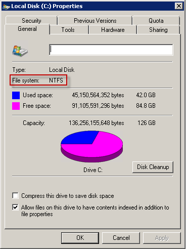
Extensive calculations may result in vast amounts of data. Of course, current hard drives and SSDs are measured in terabytes. Therefore, you expect this to be no problem for current computing technology. This is true, in fact, but as often happens, the devil is in the details.
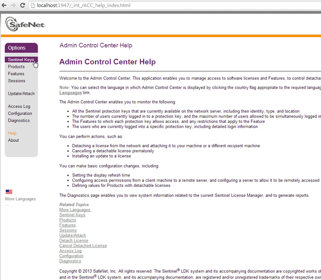
A network dongle is the appropriate solution to ensure security for licensing within companies working with several RFEM and/or RSTAB licenses. First, the dongle is placed on a central server. The licenses are then requested by RFEM and RSTAB, as well as all other stand-alone programs, from this dongle via the network.
Project data are no longer stored in large shelves, but on secure servers. Each file gets a date stamp, which shows when the file was created, modified, and opened.
If you want to apply, for example, wind loads to a circular cylinder as defined in EN 1991‑4, Clause 7.9, proceed as follows.
If you want to simulate, for example, the failure of particular structural members, you can use the "Modify stiffness" function.

In RFEM, you have the option to create and analyze cables using sheaves. For this, use the "Cable on Pulleys" member type. It is ideal for pulley systems, where the longitudinal forces are transferred via sheaves.
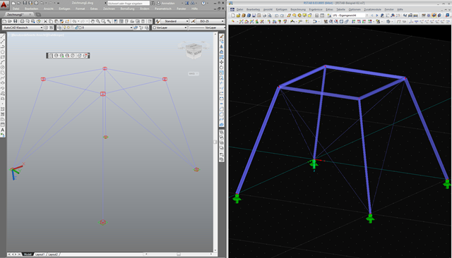
As requested by many customers, the nodes are now represented by cubes after export using the direct interface to AutoCAD or in a DXF file. If you want to reuse the AutoCAD data in RFEM or RSTAB, make sure not to import all the layers when specifying the settings for the import.
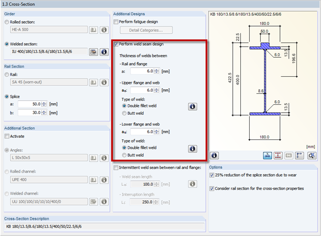
In CRANEWAY, the welds between the flanges and the web of a cross‑section are dimensioned. Options are available for defining the weld as a double fillet weld or a butt weld.
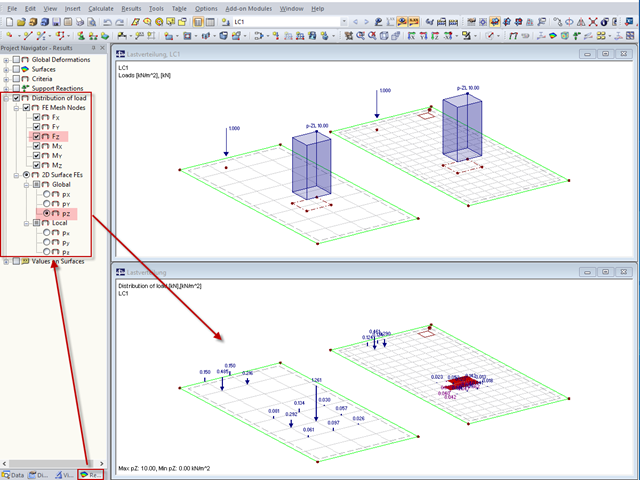
"Distribution of load" represents a load actually applied to the system of FE mesh points or FE surfaces. The FE mesh size plays an important role in the loading in the case of line loads and free loads in particular.
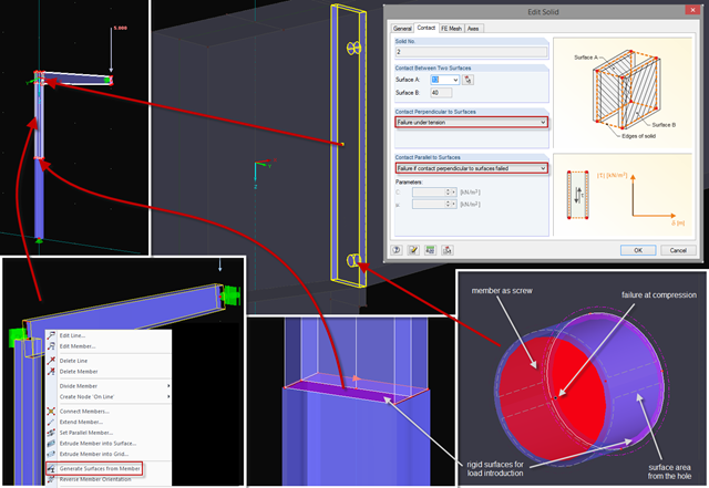
Sometimes, a detailed examination is needed of problematic areas of a joint or the stiffness of a frame joint. The following tips can help you with this. As an example, a frame joint was modeled using RF‑FRAME‑JOINT Pro and members, and used as a basis.
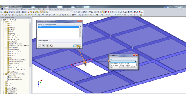
A modell check allows you to find overlapping members, among other things. However, this targeted selection could cause some minor problems. Therefore, there is a selection window now available, which appears when you click on one of the elements. This appears by clicking on one of the elements. Additional information helps you to select the correct member.
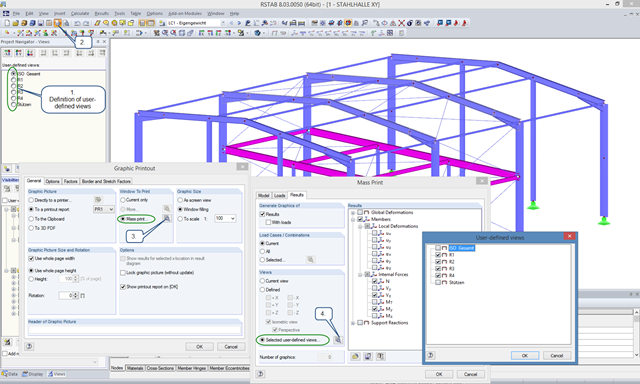
User-defined views are a very useful tool for effective modeling, as the previously selected and adapted objects appear directly with a click of the mouse. These objects can also be used easily to create informative and clearly arranged result graphics. With just a few clicks, you can create all result graphics at once using the mass print function.
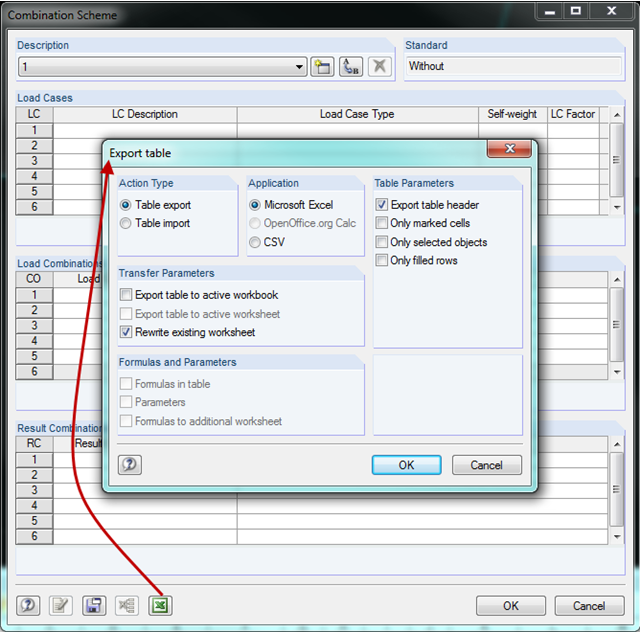
In RFEM and RSTAB, you can create a combination scheme in the combinatorics of load cases and combinations. This scheme can be used for other projects by transferring it to other computers using the Export/Import function. Thus, multiple people working on a project can use the same scheme.
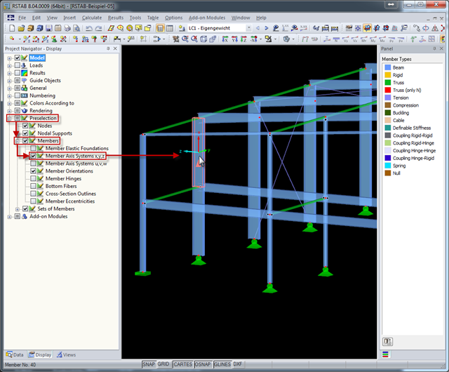
The local coordinate system of a member is particularly important when defining member end releases and member nonlinearities. The definitions follow the orientation of the axes. You can temporarily adjust the visibility of these member axes by means of preselection.
When defining real support conditions, it is always necessary to combine linear and nonlinear support conditions. This way, a beam resting on a wall can transfer compression forces to the wall and the line support (wall) will not take over the lifting forces. These forces should be carried by screws, for example, which are defined as a linear nodal support.
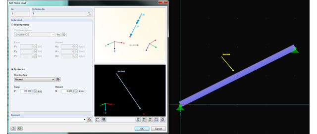
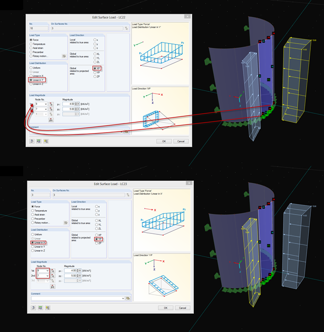
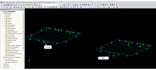
In RFEM and RSTAB, you can now rotate nodal loads or apply them on member axes. Thus, inclined members can also be loaded with nodal loads perpendicularly or along the member axis.
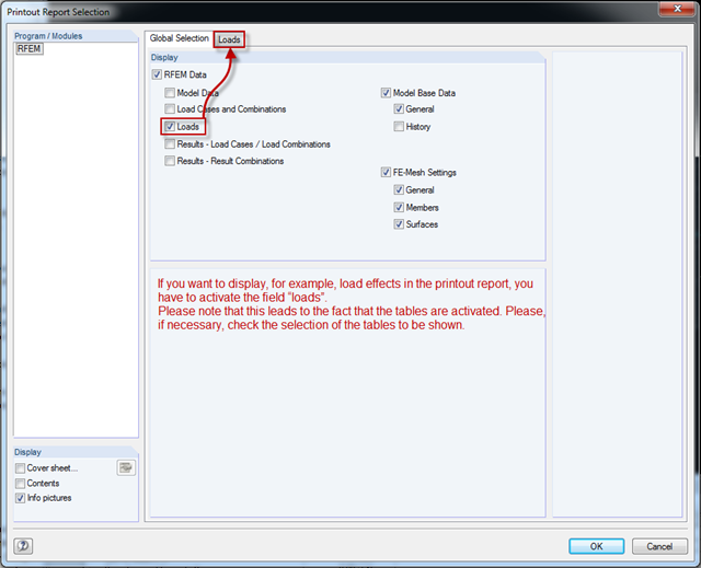
RFEM version 5.04.xx includes an adjustment when printing graphics in the printout report. In order to display graphics in the printout report, you have to select the respective check boxes in the Global Selection tab of the Printout Report Selection window (see the figure). Checking the boxes unlocks the corresponding tabs for the tables. where you can select the tables to be displayed.
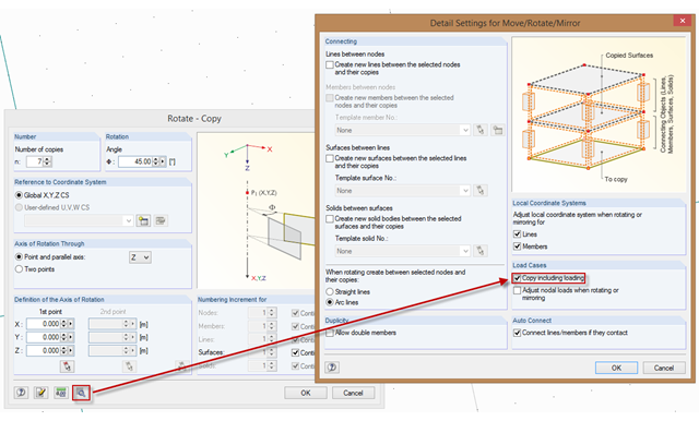
In order to also consider loading when copying, mirroring, or rotating, the corresponding option must be activated. To do this, select the corresponding check box in the "Detail Settings for Move/Rotate/Mirror" dialog box. Then, loading is included when copying until you deactivate this function.
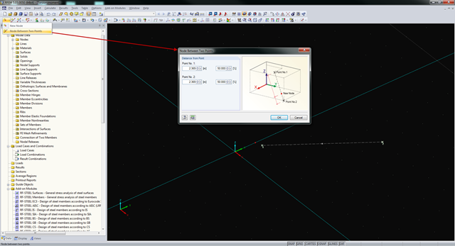
In RFEM and RSTAB, you can create nodes not only by means of coordinates, but also by means of existing nodes. You can use the "Node Between Two Points" function to create a node located on an imaginary line connecting two nodes. You can enter the distance as a percentage or according to the relative lengths.
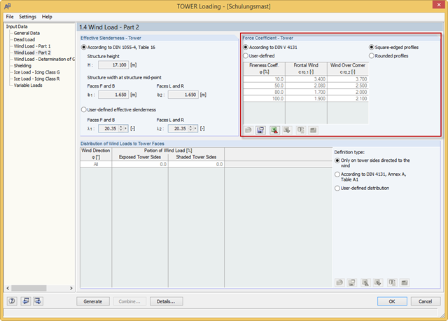
RF-/TOWER load was extended with force coefficients for rounded profiles of four-sided towers and square-edged profiles of three-sided towers. The force coefficients for rounded profiles are determined using the Reynolds number. Previously, you could only use the rounded profiles for four‑sided towers and the square‑edged profiles for three‑sided towers.
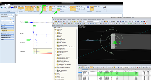
The equivalent loads determined in RF-TENDON due to prestress are transferred in RFEM as member loads or as line loads. A member load is used for member types with their own stiffness; a line load is used for member types without their own stiffness. In order to understand which values of the concentrated loads are to be transferred from RF‑TENDON to RFEM, you should use the following display settings: ~ Reference of the loads to the global coordinate system (GCS), ~ Load display: "Point"
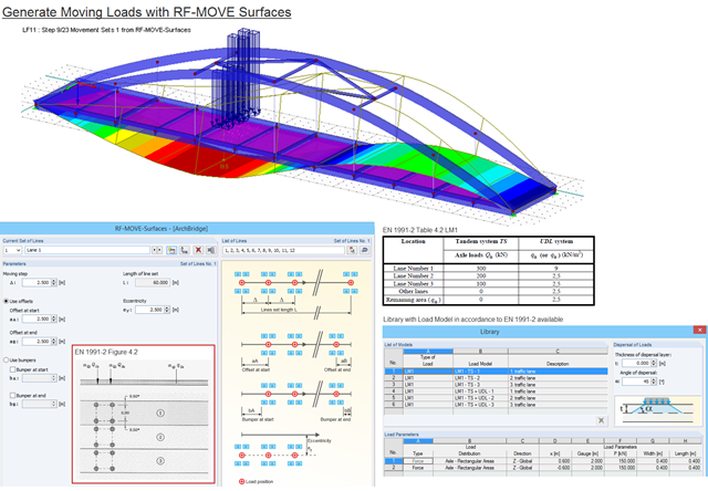
Moving loads can be generated easily with RF‑MOVE Surfaces. A library is available with load models as defined in Eurocode 1, Part 2. The input of step size, offsets at start and end, and the distance to a reference line make it possible for the user to generate user‑defined load models and influence the number of load cases generated. RF‑MOVE Surfaces generates load cases and, optionally, a result combination as an envelope of all results.
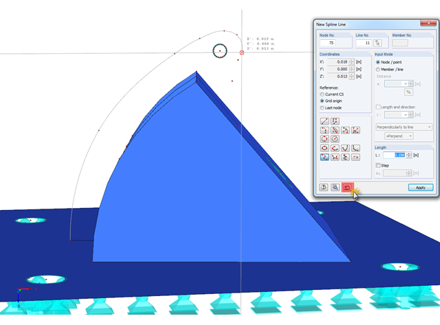
In RFEM, if you want to display a curved geometry (preferably in one continuous line), you can use splines or NURBS, for example. When modeling, you should pick the individual nodes one after another. If a mistake is made, you can go back using the special Undo function in the "New Spline Line" window. Thus, it is not necessary to enter the entire continuous line again.
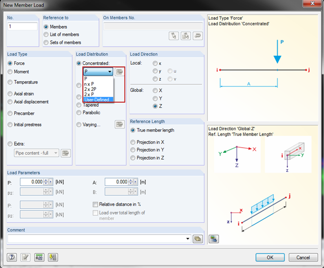
You can now also create concentrated member and line loads in RFEM and RSTAB. This is an extension of the original member/line load function. From now on, you can create several concentrated loads with uniform or user-defined load distribution on a member or a line.
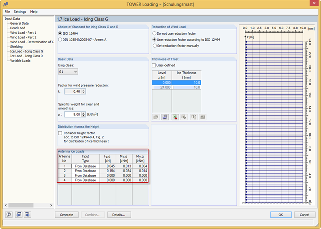
With the RFEM 5.04.0024 and RSTAB 8.04.0024 versions, you can define the antenna ice loads in RF‑/TOWER Loading. The program provides the values from the manufacturer databases. In addition, you can define the ice loads manually or use the calculation based on simplified geometry.

Diagonals of double angles are used for pipe bridge construction and for truss girders, among other things. They are usually subjected to tension, but it is necessary to transfer them in smaller compression forces with regard to the load application. In the case of slender diagonals in particular, you should also consider the bending due to self‑weight.

The new RF‑/DYNAM Pro - Natural Vibrations module has been available since RFEM version 5.04.xx and RSTAB version 8.04.xx were released. Masses can now be imported directly from load cases and load combinations.
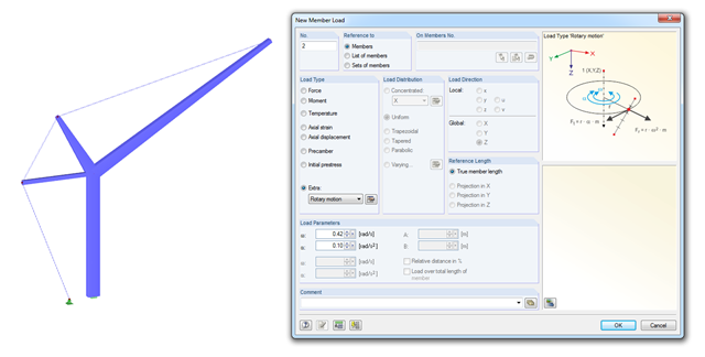
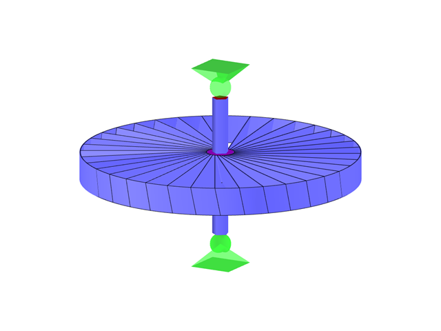
With RSTAB version 8.04.0058 and later versions, you can consider loads due to rotary motion. This load type is especially useful for crane designs (see the simplified crane in the image).
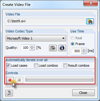
In RFEM and RSTAB, you can now create a video file of the results of all load cases, load combinations, and result combinations. Thus, you can very easily create a visual presentation of a moving load crossing a bridge, for example. This function is available under "Tools" → "Create Video File".