16 Results
View Results:
Sort by:

A new capability within RFEM 6 when designing concrete columns is being able to generate the moment interaction diagram according to the ACI 318-19 [1]. When designing reinforced concrete members, the moment interaction diagram is an essential tool. The moment interaction diagram represents the relationship between the bending moment and axial force at any given point along a reinforced member. Valuable information is shown visually like strength and how the concrete behaves under different loading conditions.

In RF-/STEEL EC3, sets of members are calculated according to the General Method (EN 1993-1-1, Cl. 6.3.4) together with the stability analysis. To do this, it is necessary to determine the correct support conditions for the equivalent structure with four degrees of freedom. In most 3D models today, you can quickly lose track of the location of a set of members in the system.

RFEM and RSTAB save the input data, the FE mesh, the results, the printout reports, and the 3D gITF model preview, including all visual objects, in one file.

In RFEM and RSTAB, you can visually check or display the materials used for members in the wireframe and solid models.

In the RF-GLASS add-on module, 3D rendering is implemented to facilitate the definition of the support conditions. This interactive graphical visualization facilitates the input and control of line and nodal supports. However, the schematic display can also be selected, if necessary.
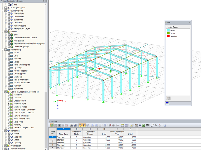
In RFEM and RSTAB, you can now also display and check the types of members used visually, by means of colors. To do this, an option has been integrated into the Display Navigator.
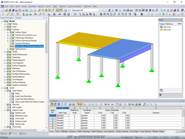
Surface thicknesses can be visualized in the model using various colors.
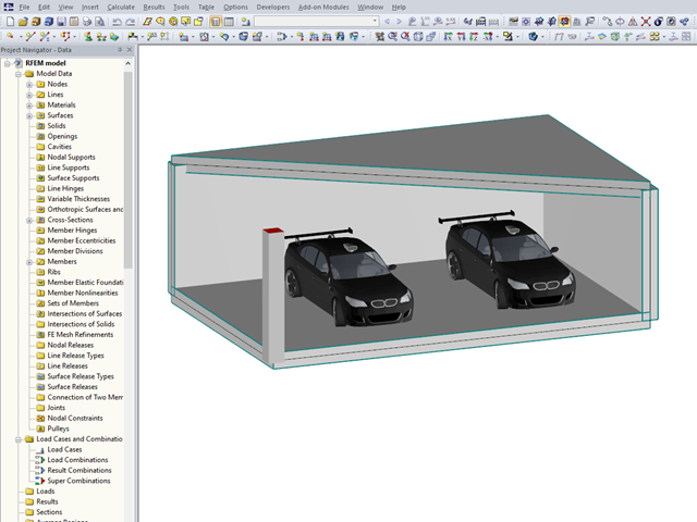
In RFEM 5 and RSTAB 8, you can add visual objects to the model in order to make a convincing impression on your client when presenting the structural model. These objects allow both laypersons and engineers to better understand the dimensions of the system.
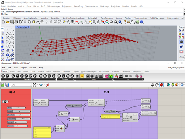
"A good tool is half the job done": This proverb could be applied equally to the software industry. The more a program is task-tailored, the more efficiently the tasks can be solved. The variety and complexity of today's problems, especially in structural engineering, require specifically tailored solutions. Creating your own programs by means of textual programming requires in-depth knowledge and a great ability to abstract. Understandably, only very few engineering offices face this challenge. For this reason, there are additional software solutions providing the user with a visual development environment.

Structures are naturally three-dimensional. However, because it was impossible to perform calculations on three-dimensional models easily in the past, the structures were simplified and broken down into planar subsystems. With the increasing performance of computers and related software, it is often possible to do without these simplifications. Digital trends such as Building Information Modeling (BIM) and new options for creating realistic visualized models reinforce this trend. But do 3D models really offer an advantage, or are we just following a trend? The following text presents some arguments for working in 3D models.
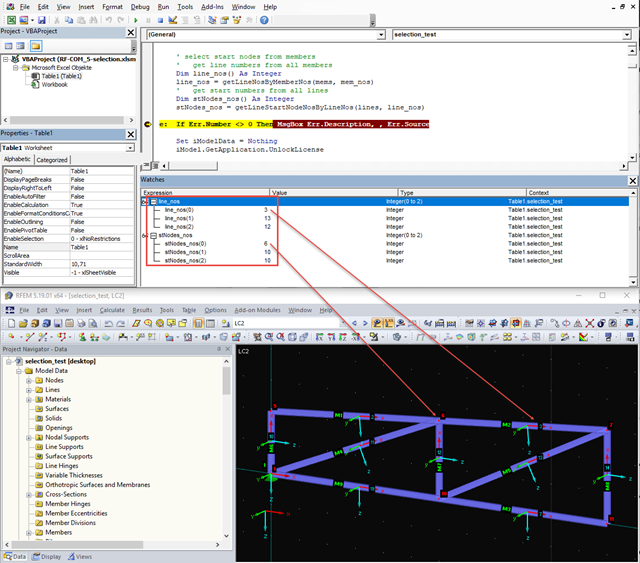
When editing elements via the COM interface, selecting elements is often a problem because it cannot be carried out visually via the work window. The selection can be particularly difficult for models that have been created via the program interface and are then to be modified using a separate program. Apart from the exception, when the selection was made previously via RFEM, there are several alternatives for programming.
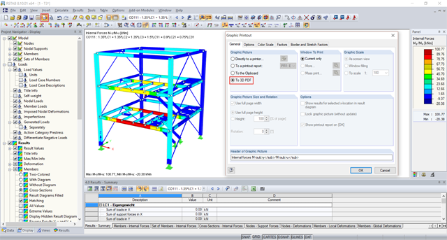
The 3D PDF functionality allows you to display three-dimensional models from RFEM or RSTAB in a 3D PDF.
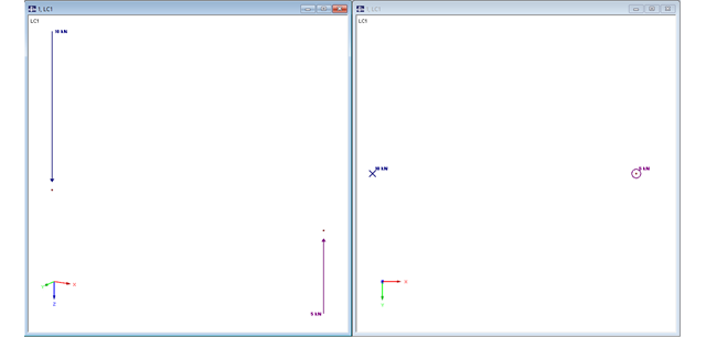
In RFEM, structures can be modeled and analyzed in a spatial environment. The permanent 3D visualization helps you to better understand complex models and to represent the force flux. However, you can switch from a spatial mode to a planar sheet mode in the documentation of a calculation. To do this, you have to describe the spatial calculation of the structure with all the necessary properties on "flat" paper pages for an independent reader. Usually, you try to display the load actions and the corresponding results by using an orthogonal view of the substructure of the entire structure. Obviously, the load symbols depicted in the 3D mode in a view perpendicular to the load become unrecognizable due the missing expansion. In order to still be able to create a clear representation of all information, the corresponding adjustments are available in RFEM.
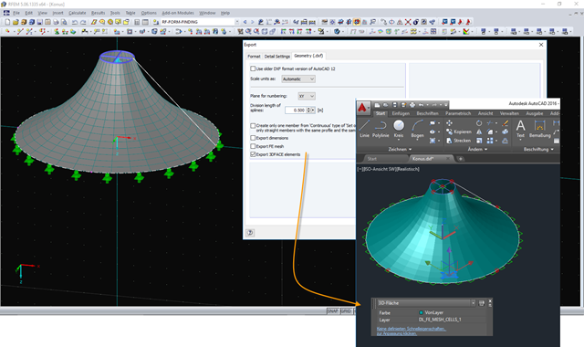
The DXF interface in RFEM now exports a 3DFACE element in the DXF file for each FE mesh cell of the exported structure. The 3DFACE element is detected by AutoCAD during import, for example, and can be displayed as a surface in the graphic. Different visual styles help display the 3DFACE surfaces in a desired view.
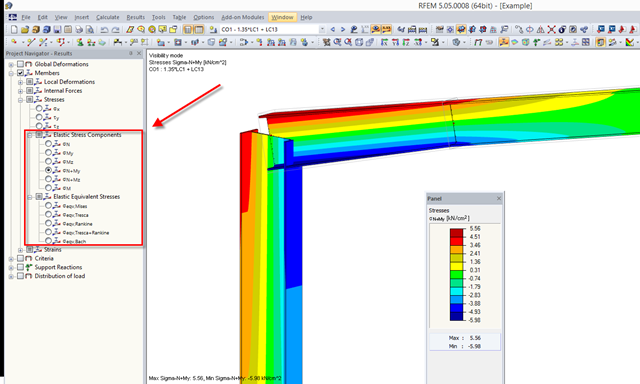
RFEM 5.04.xx allows for graphical visualization of normal and shear stress of members (this feature is available only if the RF‑STEEL add‑on module is licensed).
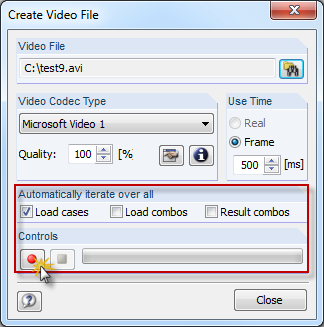
In RFEM and RSTAB, you can now create a video file of the results of all load cases, load combinations, and result combinations. Thus, you can very easily create a visual presentation of a moving load crossing a bridge, for example. This function is available under "Tools" → "Create Video File".