8 Results
View Results:
Sort by:

When a concrete slab is set upon the top flange, its effect is like a lateral support (composite construction), preventing problems of torsional buckling stability. If there is a negative distribution of the bending moment, the bottom flange is subjected to compression and the top flange is under tension. If the lateral support given by the stiffness of the web is insufficient, the angle between the bottom flange and the web intersection line is variable in this case so that there is a possibility of distortional buckling for the bottom flange.

You can color the surfaces in the direction of the local z‑axis using the indicated option in the Display Navigator. By default, the side lying in the negative z-direction is colored red and the side lying in the positive z-direction is colored blue.
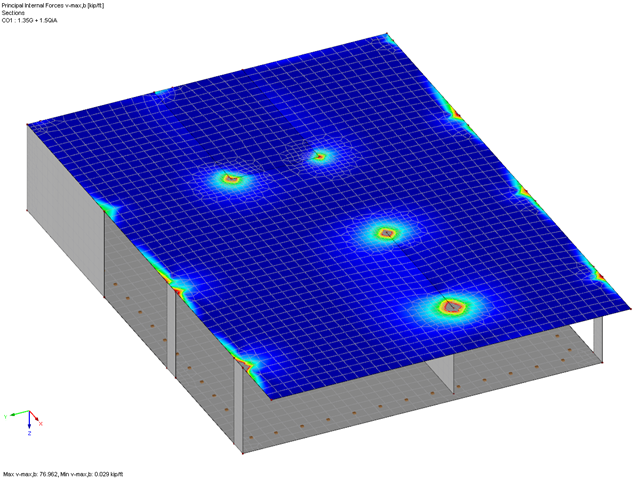
In RF-PUNCH Pro, you can perform the punching shear design on wall corners and wall ends. The basis for the design is the punching load, which is automatically determined from the RFEM internal forces in the connected surface. Since the surface internal forces from the RFEM calculation may be subject to the influence of singularity locations, this can also have a negative influence on the determined punching load at the wall corner or end. This article describes possible optimization options that you can use to minimize this unfavorable influence.
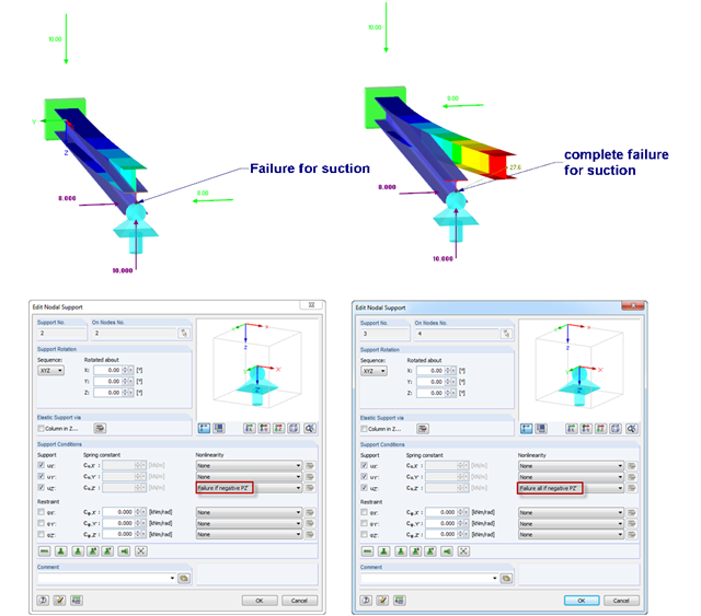
If nodal supports should have an effect in certain directions only, you can define failure. Here is an example of a single‑span beam, of which the right support can only absorb positive vertical loads. The load comprise vertical suction load and horizontal load. However, there are 2 failure options:
1) Failure if negative PZ'
2) Failure all if negative PZ'
The difference is illustrated in the graphic.
1) Failure if negative PZ'
2) Failure all if negative PZ'
The difference is illustrated in the graphic.
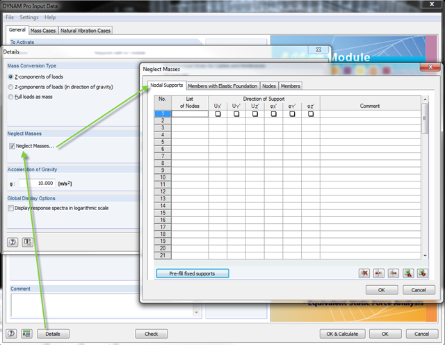
In the DYNAM Pro add‑on module for RSTAB, you can now neglect masses that may have a negative effect on the equivalent mass factor when calculating eigenvalues. To do this, you can disable the masses under [Details]. These include primarily mass points located in the support of the structures.
When accidental torsion is considered in the RF-/DYNAM Pro - Equivalent Loads module, the module exports two load cases for each eigenvalue: one with positive torsional moment, the other with negative torsional moment. The generated equivalent loads themselves do not differ in these two load cases.
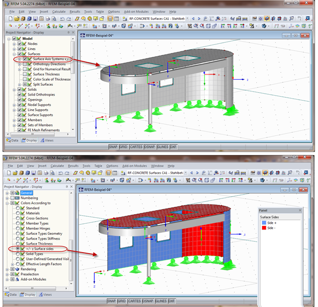
When calculating the surface reinforcement in RF-CONCRETE Surfaces, the result values for both surface sides +/- z are available. If you are unsure which side of a surface is the positive or the negative z side, you can hide the local coordinate system of each surface in the RFEM Project Navigator - Display under "Model" → "Surfaces" → "Surface Axis Systems x,y,z". In the case of complex structures, this can quickly become confusing. Displaying multiple axis systems makes it difficult to recognize the incorrect direction of a surface, for example (see the figure on the top).
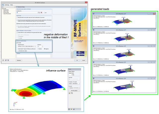
For the reduction of loads generated in RF‑MOVE Surfaces, you can consider the influence surfaces of a selected point. The influence surfaces are determined by RF-INFLUENCE. This procedure is useful in cases where only unfavorably acting loads should be considered. Depending on the unfavorable action, you should select the positive or negative direction.