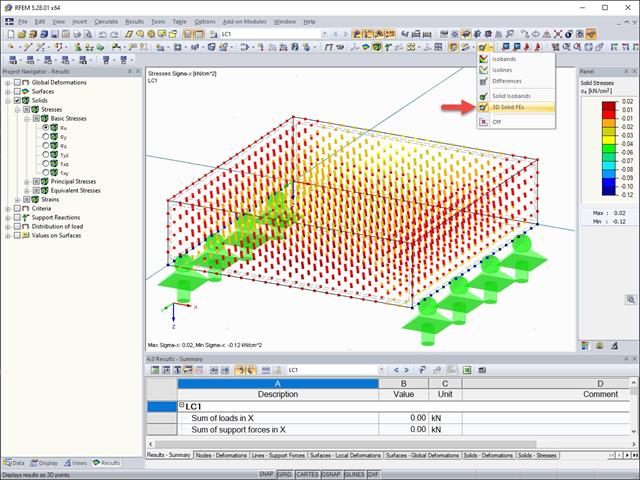
The results of solid stresses can be displayed as colored 3D points in the finite elements.
.png?mw=640&hash=9aa98962d5e0d0ed2803b35fcb6a2f87288b0946)
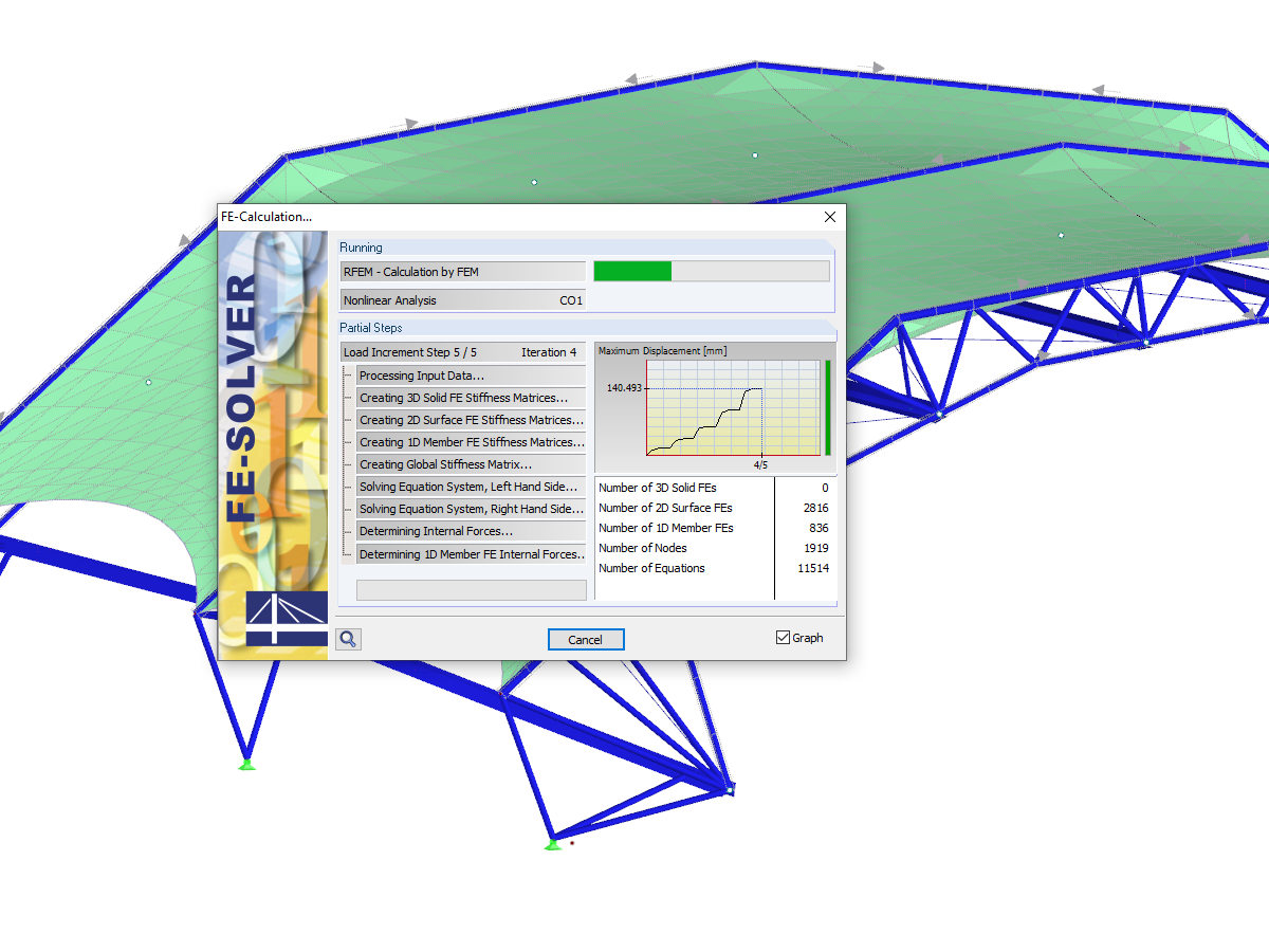
The number of degrees of freedom in a node is no longer a global calculation parameter in RFEM (6 degrees of freedom for each mesh node in 3D models, 7 degrees of freedom for the warping torsion analysis). Thus, each node is generally considered with a different number of degrees of freedom, which leads to a variable number of equations in the calculation.
This modification speeds up the calculation, especially for models where a significant reduction of the system could be achieved (for example, trusses and membrane structures).
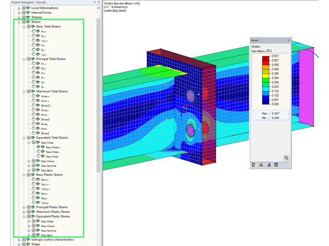
Display extended strains of members, surfaces, and solids (for example, the important principal strains, equivalent total strains, and so on) in the Project Navigator - Results in RFEM as well as in Table 4.0.
For example, you can display governing plastic strains when performing the plastic design of connections with surface elements.
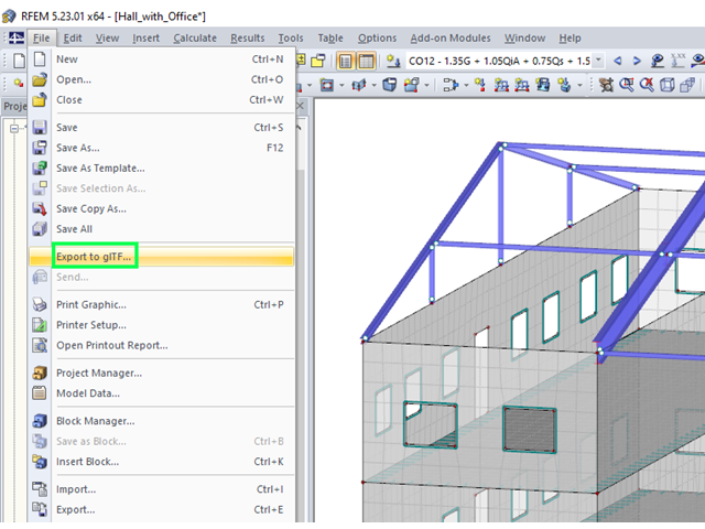
RFEM and RSTAB models can be saved as 3D glTF models (*.glb and *.glTF formats). View the models in 3D in detail with a 3D viewer from Google or Babylon. Take your VR glasses, such as Oculus, to "walk" through the structure.
You can integrate the 3D glTF models into your own websites using JavaScript according to these instructions (as on the Dlubal website Models to Download).
With the Camera Fly Mode view option, you can fly through your RFEM and RSTAB structure. Control the direction and speed of the flight with your keyboard. Additionally, you can save the flight through your structure as a video.
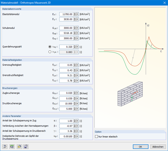
The material model Orthotropic Masonry 2D is an elastoplastic model that additionally allows softening of the material, which can be different in the local x- and y-directions of a surface. The material model is suitable for (unreinforced) masonry walls with in-plane loads.
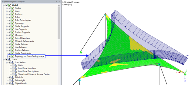
With the activated option 'Topology on Form-Finding Form' in Project Navigator - Display, the model display is optimized based on the form-finding geometry. For example, the loads are displayed in relation to the deformed system.
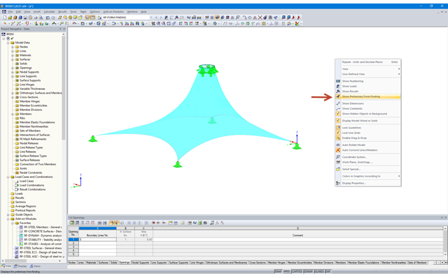
Activating 'Show Form-Finding' in the shortcut menu leads to an automatic preliminary form-finding according to the saved form-finding properties when you change the structure of membrane surfaces. This interactive graphics mode is based on the force density method.
More Information FAQ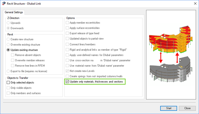
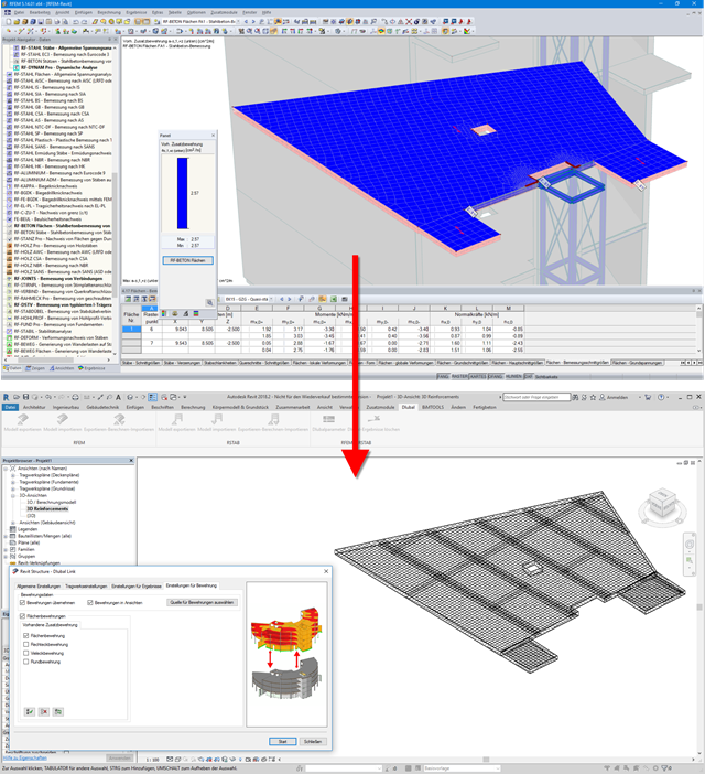
The direct interface with Revit allows you to update the Revit model according to the changes you have made in RFEM or RSTAB. Depending on the modification, the Revit objects may have to be regenerated (deleting the object and subsequent regeneration). The regeneration is performed on the basis of the RFEM/RSTAB model.
If you want to avoid this regeneration, activate the check box 'Update only materials, thicknesses, and sections'. In this case, only the properties of the objects will be adjusted. Changes different from those in material, surface thickness, and section are, however, not considered in this case.
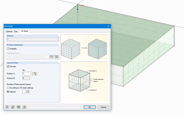
The stiffness of gas given by the ideal gas law pV = nRT can be considered in the nonlinear dynamic analysis.
The calculation of gas is available for accelerograms and time diagrams for both the explicit analysis and the nonlinear implicit Newmark analysis. To determine the gas behavior correctly, at least two FE layers for gas solids should be defined.
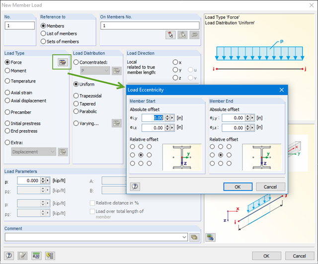
You can define eccentricities for member loads of the load type 'Force'. You can apply the load eccentricities by means of an absolute or relative offset.
We recommend using the large deformation analysis to consider all effects of eccentric loads.
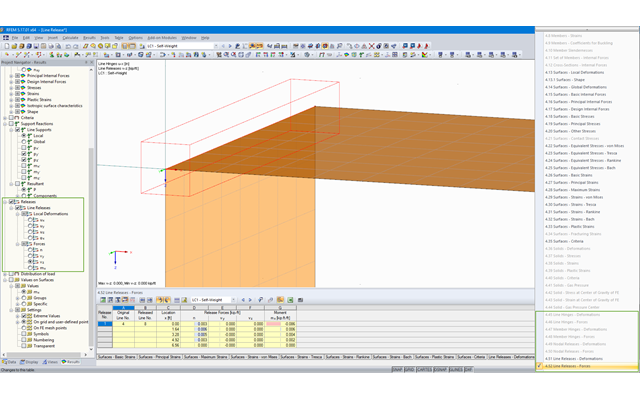
RFEM offers the following tables to display forces and deformations of hinges and releases:
- 4.45 Line Hinges - Deformations
- 4.46 Line Hinges - Forces
- 4.47 Member Hinges - Deformations
- 4.48 Member Hinges - Forces
- 4.49 Nodal Releases - Deformations
- 4.50 Nodal Releases - Forces
- 4.51 Line Releases - Deformations
- 4.52 Line Releases - Forces
The tables can be displayed in the prinout report. Moreover, the results in line hinges and line releases can be displayed graphically. It can be controlled by Project Navigator - Results.
The reinforcement proposal from RF-/CONCRETE Members can be exported to Revit. The rectangular and circular cross-sections are currently supported.
The reinforcement bars can be modified retroactively in Revit.
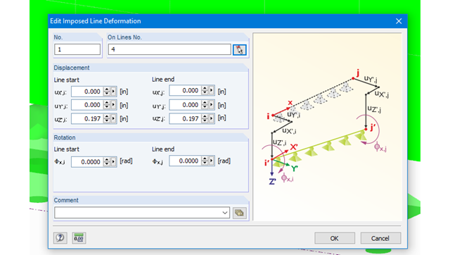
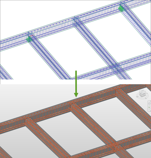
Imposed line deformations can be defined for supported lines in RFEM. For example, foundation settlements can be simulated with this function.
Moreover, it is possible to define imposed rotations for lines.
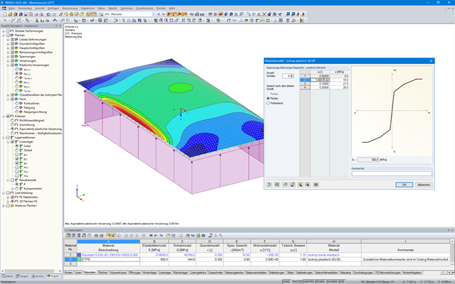
In RFEM, there is an option to couple surfaces with the stiffness types "Membrane" and "Membrane Orthotropic" with the material models "Isotropic Nonlinear Elastic 2D/3D" and "Isotropic Plastic 2D/3D" (add-on module RF-MAT NL is required).
This functionality enables simulation of the nonlinear strain behavior of ETFE foils, for example.
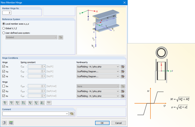
The member hinge nonlinearities "Scaffolding - N phiy / phiz" and "Scaffolding Diagram" enable the mechanical simulation of a tube joint with an inner stub between two member elements.
The equivalent model transfers the bending moment via the overpressed outer pipe and after positive locking additionally via the inner stub, depending on the compression state at the member end.
Surface reinforcements defined in the RF-CONCRETE Surfaces add-on module can be exported to Revit as reinforcement objects via the direct interface. To do this, you can optionally select surface, rectangular, polygon, and circular reinforcement areas in RF-CONCRETE Surfaces. In addition to bar reinforcement, it is possible to export mesh reinforcement.
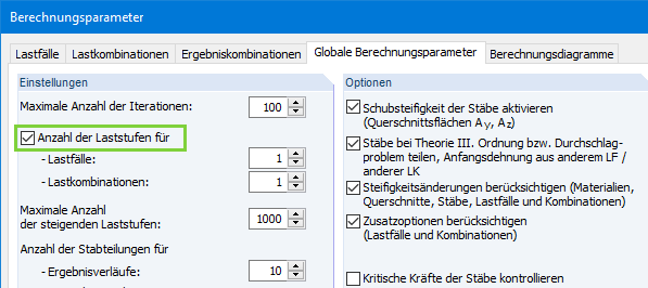
If the check box 'Number of load increments' is deactivated, the number of load increments will be determined automatically in RFEM to solve nonlinear tasks efficiently.
The method used is based on a heuristic algorithm.
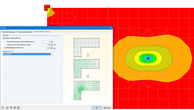
With this function, it is possible to refine the FE mesh on surfaces automatically. The mesh refinement is gradual. In each step, the FE mesh is recreated based on an error comparison of the results in the previous calculation step. The numerical error is evaluated from the results of surface elements and is based on the energy formulation of Zienkiewicz-Zhu.
The error evaluation is carried out for a linear static analysis. We select a load case (or load combination) for which the FE mesh is generated. The FE mesh is then used for all calculations.
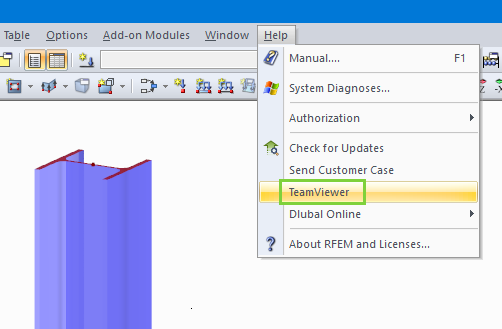
It is possible to access the TeamViewer directly by opening the Help menu of RFEM and RSTAB. Customers with Service Contract Pro can thus benefit from easy and quick online support via video conference.
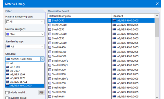
The material database in RFEM, RSTAB and SHAPE-THIN contains steels according to the Australian standard AS/NZS 4600:2005.
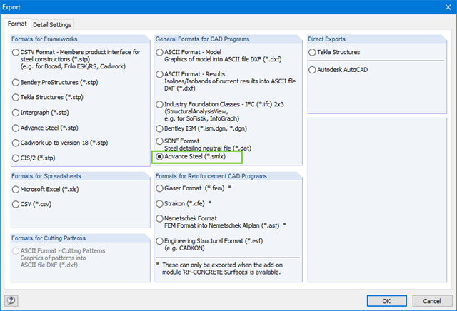
When exchanging data with Advance Steel using *.smlx files, the interface is detected automatically. This means that *.smlx files can be created even if no version of Advance Steel is installed.
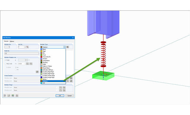
The member type 'Dashpot' can be used for time history analyzes in RFEM/RSTAB with the add-on modules RF-/DYNAM Pro - Forced Vibrations and RF-/DYNAM Pro - Nonlinear Time History. This linear viscous damping element considers forces dependent on velocity.
With regard to viscoelasticity, the member type 'Dashpot' is similar to the Kelvin-Voigt model, which consists of the damping element and an elastic spring (both connected in parallel).
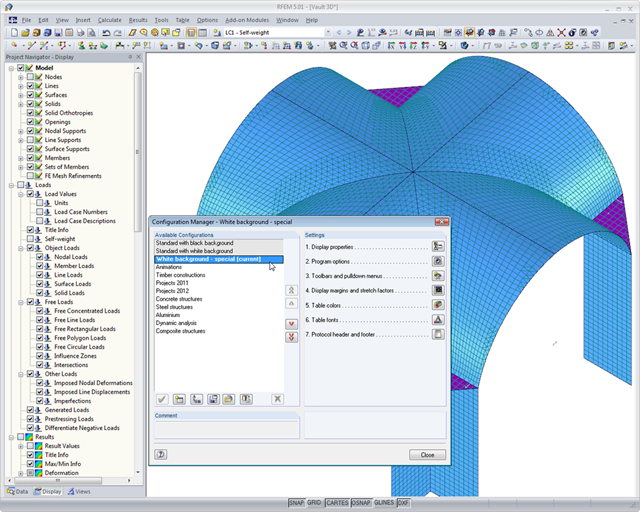
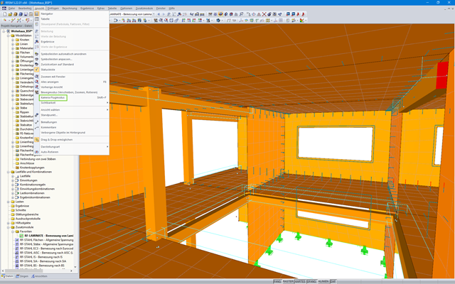
If you are interested in making your daily work easier and more efficient, you should also pay attention to this feature. Program configuration menus and toolbars can be freely customized. This allows you to arrange your frequently used functions in a user-defined way and save time. Everything from the beginning? No problem: You can restore the default settings of the program with a mouse click. Tables, navigators, and toolbars can also be moved and docked as required.
Furthermore, you can use the configuration manager to set the graphic display properties, toolbars, and so on in a user-defined way and save them as your own configuration. Thus, the software becomes your individual productivity enhancer.
Dlubal Software customers come from all over the world and there are, of course, numerous language options for the structural analysis software. It is possible to operate the program in the following languages: English, Chinese, Czech, Dutch, French, German, Italian, Polish, Portuguese, Russian, and Spanish.
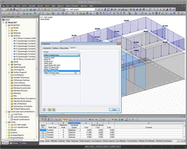
You can also modify the design of the RFEM/RSTAB user interface: There are nine different styles of graphical user interface to choose from; for example: Office 2007 Blue, Silver, Aqua, and Black. Customize the programs to your individual needs.
The Dlubal programs are user-friendly. This way, you will have a short induction period and easy handling of the software.
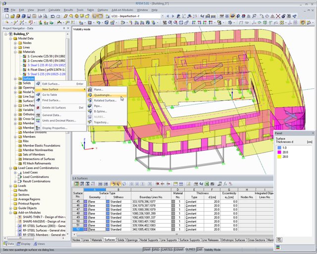
Your structure is created in a user interface usual for CAD or via tables. By right-clicking the graphical or navigator objects, you can activate a shortcut menu that allows you to easily create or modify the objects. Try it out for yourself and let yourself be inspired by the intuitive user interface! Therefore, you can create the structural and loading objects in a minimum amount of time.
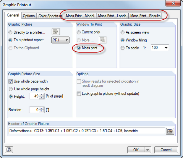
You also have many useful options for printing. You can mass print the model, loads, and results. In this case, it is possible to create graphics from different defined directions. For example, you can print all internal forces as an isometric view with just a single mouse click. This way, you can always keep track of things.
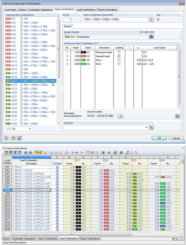
Utilize all the options of the 'Edit Load Cases and Combinations' dialog box to facilitate your work. Here you can automatically create load and result combinations after selecting the corresponding combination expressions. In this clearly arranged dialog box, you can also e.g. to copy, add, or renumber load cases.
Additionally, control the load cases and combinations in Tables 2.1 – 2.6.
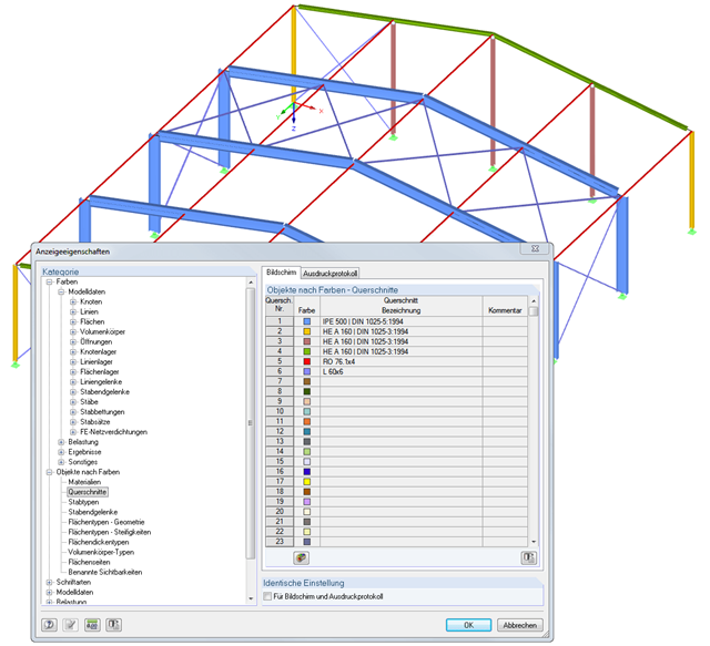
Always keep track of things by assigning different colors to the various objects in your structure. Thus, the rendering display of the structure is even clearer; and you can see the essentials at a glance.
You can distinguish between Materials, Cross-Sections, Member Types, Member Hinges, Surface Types - Geometry, Surface Types - Stiffness, Surface Thicknesses, Solid Types, Surface Sides, Named Visibilities, and Effective Length Factors.
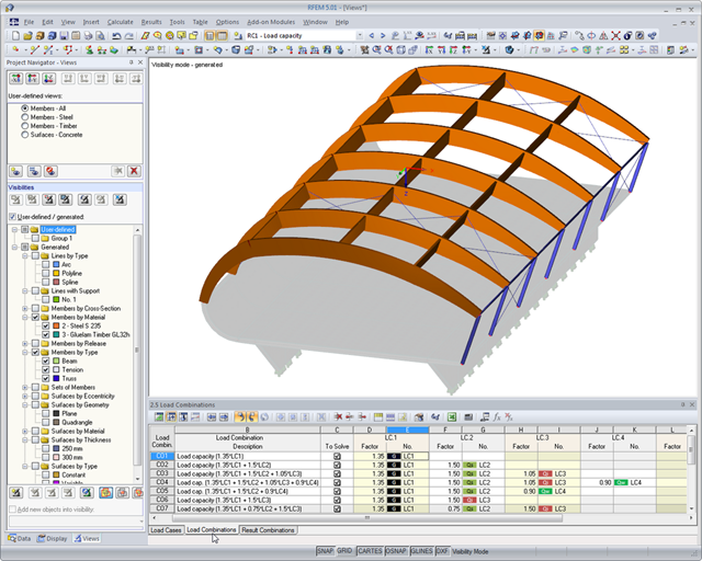
Use Project Navigator - Views to generate views quickly and easily. You can save it and open it again at any time, if necessary.